sprinkler head

A technology of sprinkler heads and sprinkler holes, applied in fire rescue and other directions, can solve the problems of increasing capacity, increasing the amount of water spraying, unable to obtain the amount of water and spraying water distribution, etc., to achieve the effect of increasing the splashing distance and expanding the protection area.

Active Publication Date: 2017-08-29
SENJU SPRINKLER
View PDF1 Cites 0 Cited by
  • Summary
  • Abstract
  • Description
  • Claims
  • Application Information

AI Technical Summary

Problems solved by technology

[0007] The water sprayed from the above-mentioned sprinkler head is water droplets of a certain size or more, so it is easy to drop from the height where the sprinkler head is installed to the floor surface, but in the case of expanding the protection area, it is necessary to use The spray pressure and water spray volume of the sprinkler head increase, so that the splash distance of the water sprayed from the sprinkler head in the horizontal direction increases, or the spray water volume sprayed into the expanded protection area increases
However, if the water spray pressure and water spray volume are increased, there is a problem that the size of the piping connecting the water source and the water spray head must be increased, and the capacity of the pump for supplying water to the water spray head must be increased, resulting in an increase in equipment cost.
[0008] On the other hand, if the size of the water droplets sprayed from the sprinkler head is reduced, although the splashing distance of the water droplets in the horizontal direction increases, but due to the influence of air resistance and air conditioning equipment, the water is sprayed to places outside the protected area. Or the spray water distribution is not uniform in the protected area, so that the water volume and spray water distribution above the regulations stipulated by the law may not be obtained

Method used


Image

  • sprinkler head
  • sprinkler head
  • sprinkler head

Examples


no. 1 approach

[0033] The first embodiment ( Figure 1 to Figure 3 )

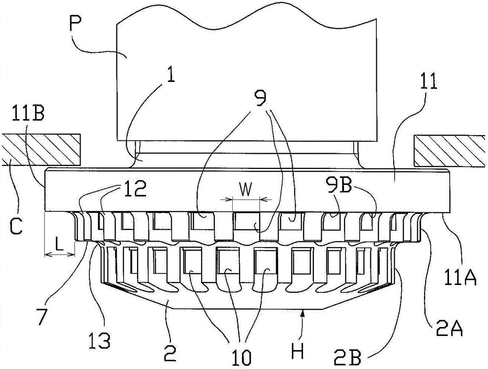
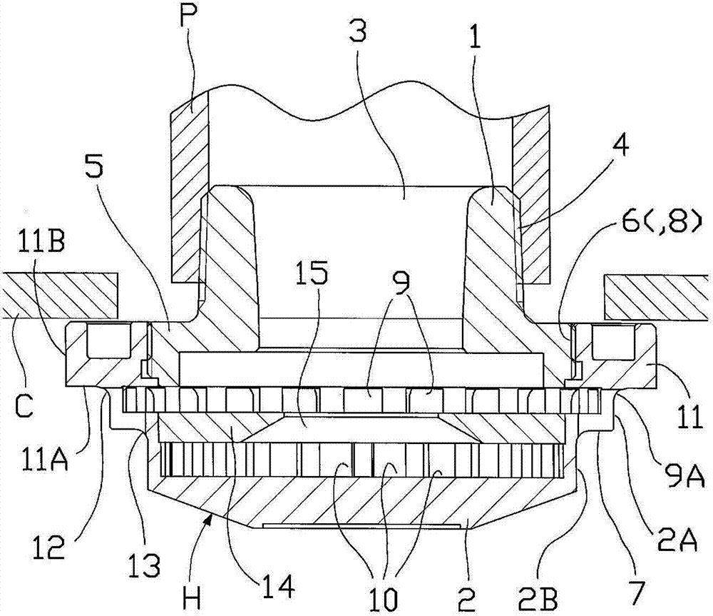
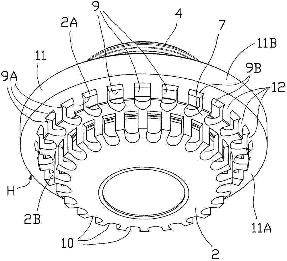
[0034] The sprinkler head H of the first embodiment is composed of a main body 1 and a deflector 2 . The main body 1 has a cylindrical shape, and a water outlet 3 is formed in the center, and a mounting screw 4 for mounting on a pipe P is provided on the outside of the water outlet 3 . A flange 5 is formed on the lower portion of the main body 1 , and an external thread 6 is provided on the outer peripheral portion of the flange 5 .

[0035] The deflector 2 is formed in a bowl shape having a stepped portion 7 on the outer periphery thereof, and a female thread 8 is provided on the upper inner periphery of the deflector 2 . The deflector 2 is attached to the main body 1 by screwing the internal thread 8 to the external thread 6 of the flange 5 of the main body 1 . A plurality of water spray holes (upper water spray holes) 9 are arranged in an annular arrangement above the step portion 7 on the deflector 2 . In addition...

Deformed example 1

[0043] Variation 1 ( Figure 4 )

[0044] exist Figure 4 In Modification 1 shown, the lower surface 11A of the flange portion is inclined upward (in the direction of the ceiling C) from the upper spray hole 9 toward the outer edge portion 11B of the flange portion 11 . The outer edge portion 11B of the flange portion 11 is arranged close to the lower surface of the ceiling C, so as to reduce the resistance of the water flowing through the flange portion 11 to the lower surface of the ceiling C, thereby increasing the splashing distance in the horizontal direction. .

[0045] In addition, when the ceiling C is not provided, when the water sprayed from the upper water spray hole 9 flows along the lower surface 11A of the flange portion 11 and splashes from the outer edge portion 11B, it forms a water flow obliquely upward and splashes. It is thereby possible to increase the splash distance in the horizontal direction.

Deformed example 2

[0046] Variation 2 ( Figure 5A , 5B )

[0047] In Modification 2, a groove G is provided on the lower surface 11A of the flange portion 11 from the outlet of the upper spray hole 9 toward the outer edge portion 11B of the flange portion 11 . As a result, the water sprayed from the upper water spray hole 9 flows along the groove G, so that the amount of water sprayed in any direction can be increased or the splashing distance can be increased.

[0048] exist Figure 5A Among them, a groove G is provided in any direction on the lower surface 11A of the flange portion 11 . This guides the water flow along the direction in which the groove G extends, so that an elliptical protected area can be formed. In addition, in Figure 5B In the center, a groove G curved in an arc shape is provided, and the water sprayed from the upper spray hole 9 flows along the groove G, and the water splashed from the outer edge portion 11B is sprayed while swirling in a spiral shape. Thereby, the...


PUM


Abstract

The invention provides a water spray head which can ensure the size of sprayed drops and increase the spraying distance along the horizontal direction to enlarge the protective area. A mutli-head type water spray head is arranged on a plurality of water spray holes (9,10) on a bowl-shaped flow guide plate (2) in a penetrating way and arranged in a circular way. The water spray holes arranged in a circular way are arranged on a plurality of ladder parts in a penetrating way. The flow guide plate (2) is arranged on the main body of a water flow port (3). The upper part of the uppermost water spray hole (9) is provided with a flange part (11).

Description

technical field [0001] The present invention relates to a sprinkler head for spraying water to extinguish a fire when a fire occurs, and more particularly to a water sprinkler head. Background technique [0002] The sprinkler head is one of the open type heads whose nozzles are usually open, and water is sent to the sprinkler head by the action of a fire detector or a fire sensor. The sprinkler head is installed on a higher part of the ceiling than a normal closed type sprinkler head (a sprinkler head in which the nozzle is usually closed and the thermal decomposition part is activated by the heat of the fire to open the nozzle). If the enclosed sprinkler head is installed in a high ceiling, it will take time for the heat of the fire to reach the ceiling to activate the enclosed sprinkler head, which may spread the fire. [0003] In such a high-ceiling building, an open head is used for initial fire extinguishing. Among the open type heads, the sprinkler heads are installe...

Claims


Application Information

Patent Timeline
Patent Type & Authority Patents(China)
IPC IPC(8): A62C31/02
Inventor 千叶亮太郎
Owner SENJU SPRINKLER
Why Eureka
Try Eureka