Telescoping mechanism

A telescopic mechanism and telescopic direction technology, applied in mechanical equipment, membrane boxes, etc., can solve the problems of high cost, complicated processing, inconvenient use, etc., and achieve the effect of free shrinkage and convenient use.

Inactive Publication Date: 2013-06-26
万军
View PDF7 Cites 3 Cited by
  • Summary
  • Abstract
  • Description
  • Claims
  • Application Information

AI Technical Summary

Problems solved by technology

[0002] There are many kinds of telescopic mechanisms at present, such as electric, pneumatic, hydraulic drive, etc., but no matter what kind of driving mode of the telescopic mechanism, the components that constitute the mechanism itself are all connected by mechanical parts, the processing is complicated, the cost is high, and The field of use is also subject to certain restrictions, and it is inconvenient to use in many fields
At present, there is a mechanism that can realize stretching by inflation, but the mechanism cannot be automatically retracted under exhaustion

Method used


Image

  • Telescoping mechanism
  • Telescoping mechanism
  • Telescoping mechanism

Examples


Embodiment 1

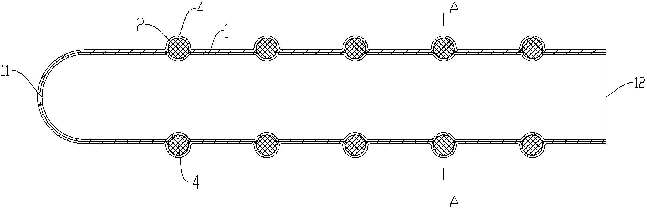
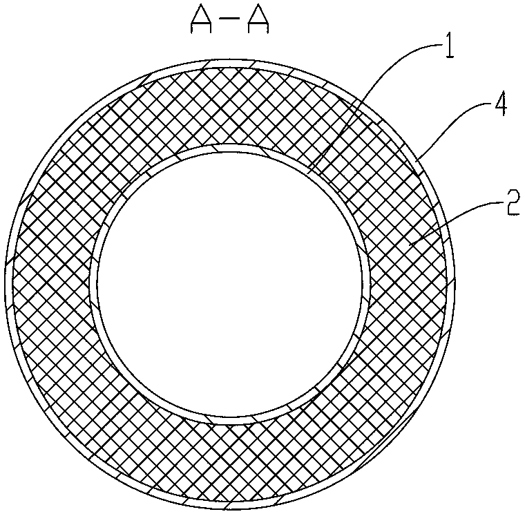
[0031] Embodiment one: if figure 1 , 2 As shown, the telescopic mechanism includes an airbag 1; one end of the airbag 1 in a set telescopic direction is set as a closed end 11, and the other end is set as an air intake end 12; A support member 2, the support member 2 supports the airbag 1 in a plane perpendicular to the telescopic direction; a space 3 for expansion and contraction is provided between every adjacent two support members 2 in the telescopic direction. The interval 3 refers to the gap between two supporting parts, that is, the space, and does not refer to any part.

[0032] In this embodiment, the support member 2 is fixed outside the airbag 1 . Each support member 2 is provided with a through hole 21 which can be nested and fixed on the airbag 1 .

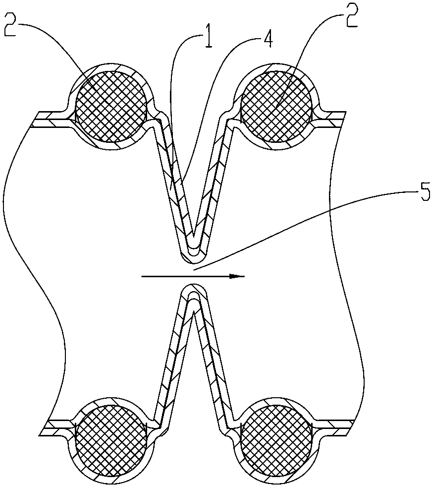
[0033] When gas is inflated into the airbag 1 from the air intake end 12, the airbag 1 is gradually stretched out as the amount of gas charged increases, and the multiple support members 2 are gradually separated t...

Embodiment 2

[0041] Embodiment two: if Figure 7 , 8 As shown, the difference between this embodiment and the first embodiment is that: the support member 2 is fixed inside the airbag 1; each support member 2 is provided with a through hole 21 along the stretching direction of the airbag.

[0042] The spacing distance between adjacent two supporting parts 2 is less than the diameter of the through holes on the two supporting parts at the two ends of the space, such as Figure 9 As shown, it can not only ensure the coherence and reliability of the contraction, but also ensure that the ventilated airway 5 is retained after the contraction, so as to prevent the airway 5 from being closed, resulting in incomplete contraction.

[0043] Preferably: the supporting member 2 is a supporting ring 7, such as an expanding ring. The supporting ring is correspondingly fitted with a snap ring 6 , and the wall of the airbag 1 is clamped between the supporting ring and the snap ring 6 . This kind of fix...

Embodiment approach

[0048] Other implementations: such as Figure 13As shown, the shapes of the supporting parts 2 are different. The shapes of the supporting parts 2 and the airbag 1 of this embodiment are all crescent-shaped, and the rest of the techniques are the same as in the first embodiment. The support component of this shape is very suitable for the needs of the field of prosthetics, and can complete the profiling of the human body such as the hand. The telescoping mechanism acts as a muscle in the prosthesis. The rest of the techniques can be the same as those in Embodiment 1 or 2, and will not be repeated here.

[0049] In addition, the shape of the support member and the airbag can be designed arbitrarily as required.

[0050] In addition: if Figure 14 As shown, each support member 2 in this embodiment is provided with a card slot 22, and the airbag 1 is fixed in the card slot 22 of the support member; and all support members 2 are located on the same side of the thin-walled long ...


PUM


Abstract

The invention discloses a telescoping mechanism. The telescoping mechanism is characterized by comprising an air bag. A closed end is arranged at one end of the air bag along a set telescopic direction, and the other end of the air bag is provided with an air intake end. A plurality of supporting parts are arranged and fixed on the air bag along the telescopic direction. The supporting parts support the air bag on a surface which is perpendicular to the telescopic direction. A gap for telescoping is arranged on every two adjacent supporting parts along the telescopic direction. The telescoping mechanism is simple in structure, easy to drive, capable of achieving automatic contraction through exhausting, free to contract, capable of being controlled and very convenient to use.

Description

technical field [0001] The invention relates to a mechanism for expanding and contracting by pneumatic force. Background technique [0002] There are many kinds of telescopic mechanisms at present, such as electric, pneumatic, hydraulic drive, etc., but no matter what kind of driving mode of the telescopic mechanism, the components that constitute the mechanism itself are all connected by mechanical parts, the processing is complicated, the cost is high, and The field of use is also subject to certain restrictions because it is easy to use, and it is inconvenient to use in many fields. At present, there is a mechanism that can realize stretching by inflation, but the mechanism cannot be automatically retracted under exhaustion. Contents of the invention [0003] In order to overcome the disadvantages of the above-mentioned prior art, the object of the present invention is to provide a telescopic mechanism, which has a simple structure and is easy to drive, and can realize...

Claims


Application Information

Patent Timeline
Patent Type & Authority Applications(China)
IPC IPC(8): F16J3/04
Inventor 万军
Owner 万军
Why Eureka
Try Eureka