
Automobile rear floor crossbeam part die

A rear floor and beam technology, which is applied in the mold field of automotive rear floor beam parts, can solve the problems of increased maintenance and replacement costs, a large number of operators, and low production efficiency, and achieves low production costs, reduced production costs, and cost savings.

Inactive Publication Date: 2013-07-03
SHANGHAI ZHONGDA AUTO PARTS
View PDF5 Cites 10 Cited by
  • Summary
  • Abstract
  • Description
  • Claims
  • Application Information

AI Technical Summary

Problems solved by technology

At present, the mold of this kind of parts is divided into two processes of punching and edge trimming. Two punches are required during production, which requires a large number of operators, high manufacturing cost, long manufacturing cycle, and low production efficiency.
The existing upper mold presser uses spring or nitrogen spring as the power source, and the spring or nitrogen spring will be damaged normally and require regular replacement, and the maintenance and replacement costs during the production process will be greatly increased

Method used


Image

  • Automobile rear floor crossbeam part die

Examples


Embodiment

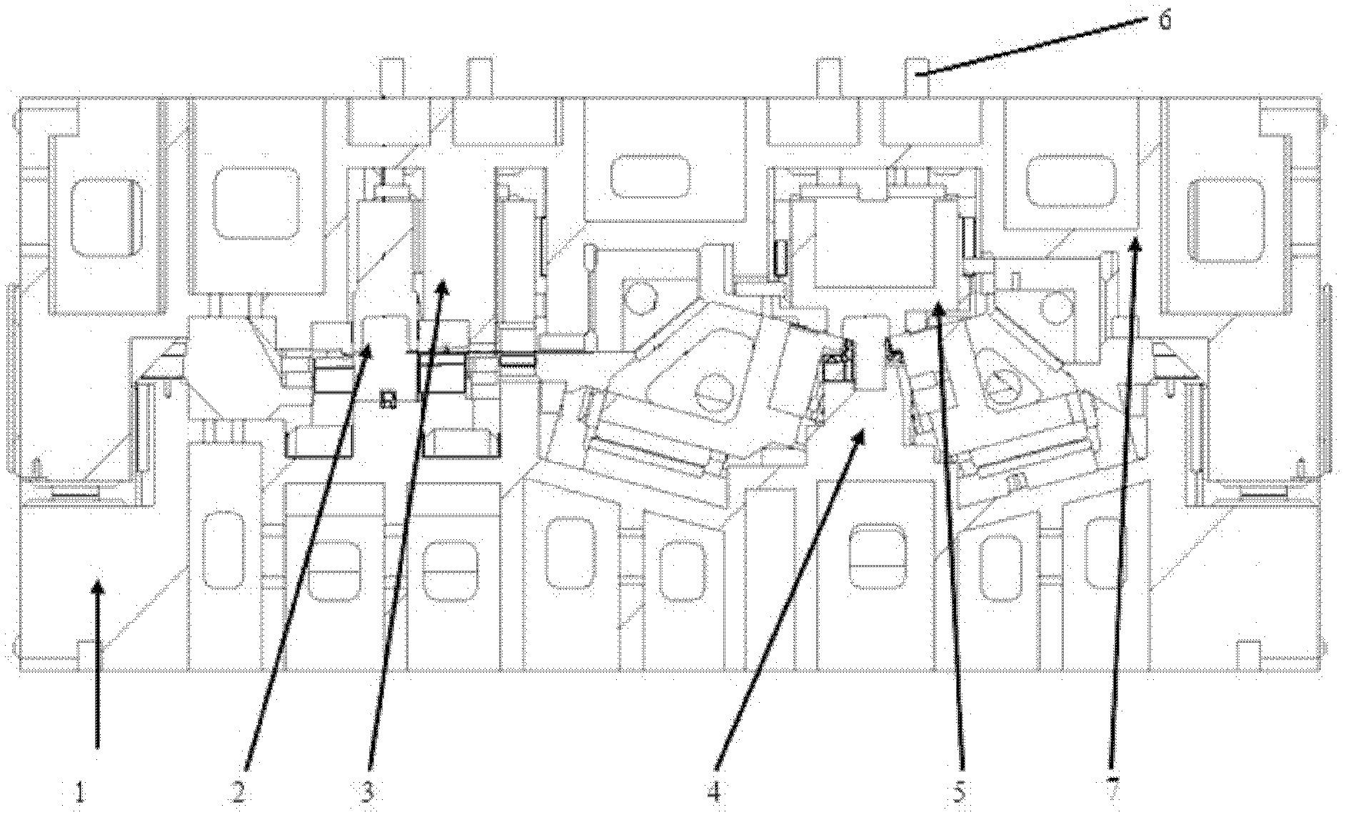
[0015] Such as figure 1 Shown, a kind of automotive rear floor crossbeam part mould, comprises lower mold and patrix, and lower mold comprises lower mold base 1, lower mold core and ejector, lower mold core and ejector are arranged on the lower mold base, lower mold The trimming and punching punch 2 and the flanging shaping punch 4 are sequentially arranged on the core; the upper die includes an upper die base 7, an upper die core, an upper die insert, an upper die presser and an upper ejector pin 6, and the upper die core is arranged on the upper die Below the mold base, on the upper mold core, set the trimming punching die 3 and the flanging shaping die 5 in sequence, the trimming punching punch 2 corresponds to the trimming punching die 3, the flanging shaping punch 4 corresponds to the flanging shaping die Die 5 corresponds. Upper ejector pin 6 is provided with 4, is dispersedly arranged on the top of upper mold base 7.

[0016] The working principle of the above automob...


PUM


Abstract

The invention relates to an automobile rear floor crossbeam part die. The die comprises a lower die and an upper die. The lower die comprises a lower die base (1), a lower die core and an ejection system, wherein the lower die core and an ejector are arranged on the lower die base. The lower die core is sequentially provided with a trimming piercing male die (2), a flanging sizing male die (4) and a side piercing male die (7). The upper die comprises an upper die base (9), an upper die core, an upper die insert, an upper die pad and an upper ejector pin (6), wherein the upper die core is arranged below the upper die base, the upper die core is sequentially provided with a trimming piercing female die (3), a flanging sizing female die (5) and a side piercing female die (8), and the upper ejector pin (6) is arranged above the upper die base (9). Compared with the prior art, the die disclosed by the invention has the advantages of low production cost, safety, reliability and the like.

Description

technical field [0001] The invention relates to a mold for producing automobile parts, in particular to a mold for automobile rear floor beam parts. Background technique [0002] The rear floor beam is a part welded on the rear floor of the car. Its function is to strengthen the strength and rigidity of the rear floor of the car and improve the torsion and mode of the car body. At present, the mold of this kind of parts is divided into two processes of punching and edge trimming, which requires two punches during production, requires a large number of operators, high manufacturing cost, long manufacturing cycle, and low production efficiency. The existing upper mold presser uses a spring or nitrogen spring as a power source, and the spring or nitrogen spring will be damaged normally and requires regular replacement, and the maintenance and replacement costs during the production process will be greatly increased. Contents of the invention [0003] The purpose of the prese...

Claims


Application Information

Patent Timeline
Patent Type & Authority Applications(China)
IPC IPC(8): B21D37/10
Inventor 李春明吴天宝沈玉林丛培民张平谢晓红范泓蔡永峰
Owner SHANGHAI ZHONGDA AUTO PARTS
Learn More