Sliding track device

A technology of slide rails and sliders, applied in the direction of bearings, linear motion bearings, shafts and bearings, etc., can solve the problems of inconvenient production and assembly, complex structure, etc., and achieve the effect of reasonable structure, smooth movement and ingenious design

Active Publication Date: 2013-07-03
邳州市承鼎机械设备有限公司
View PDF5 Cites 6 Cited by
  • Summary
  • Abstract
  • Description
  • Claims
  • Application Information

AI Technical Summary

Problems solved by technology

However, its structure is complicated, and it is inconvenient to produce and assemble, so its structure needs to be further improved.

Method used


Image

  • Sliding track device
  • Sliding track device
  • Sliding track device

Examples


Embodiment 1

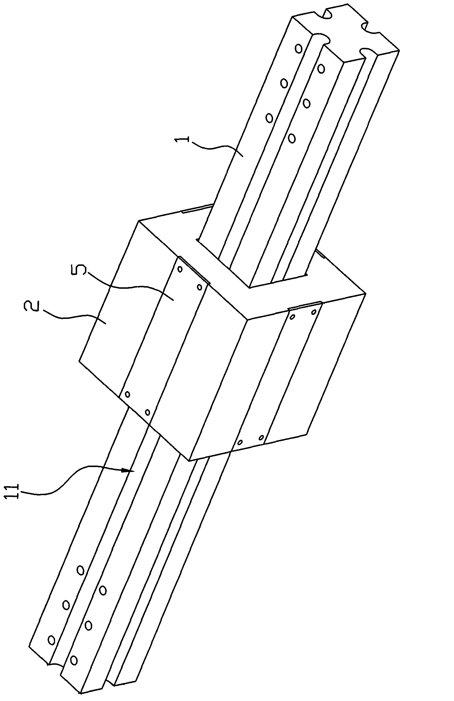
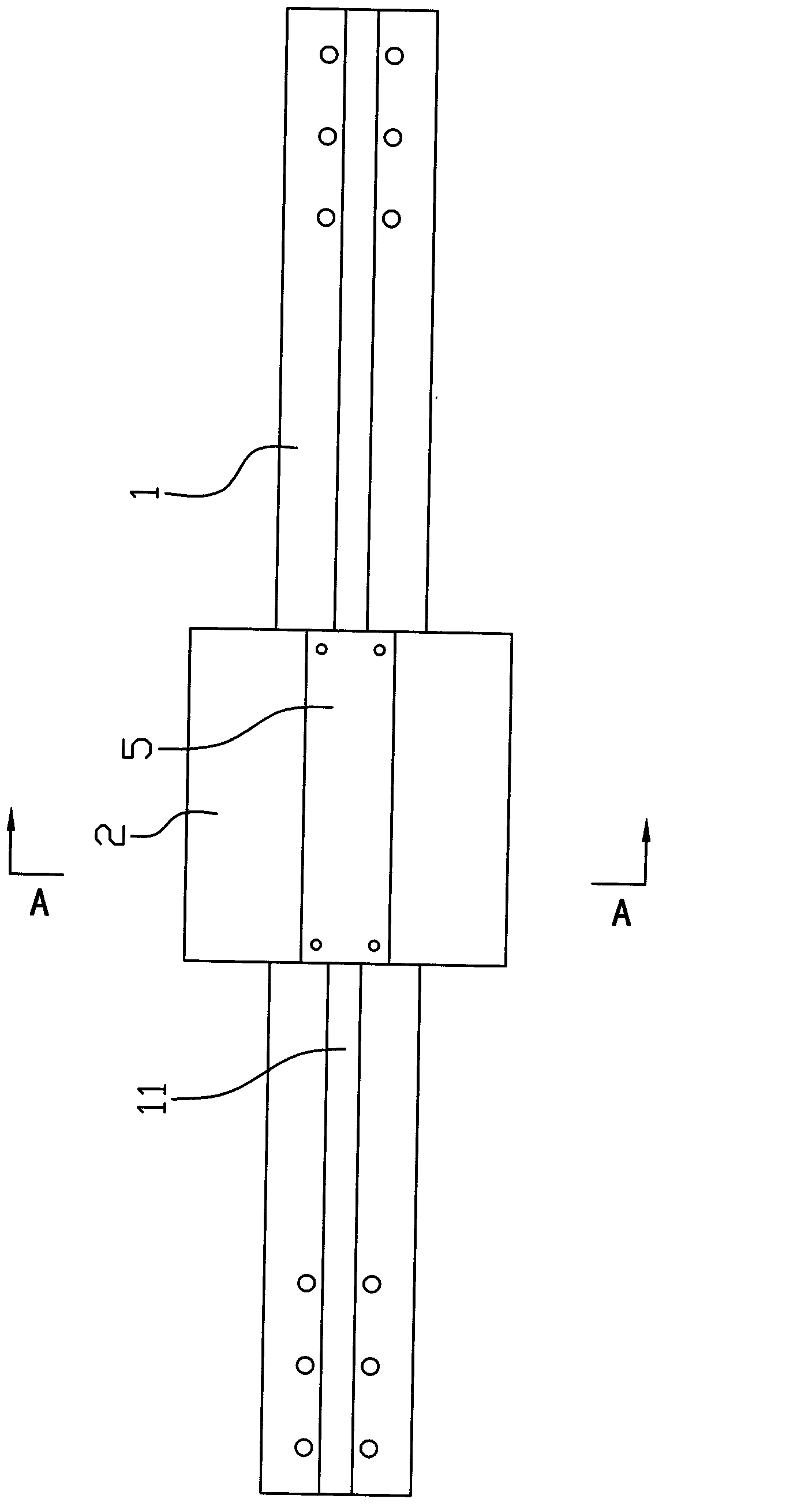
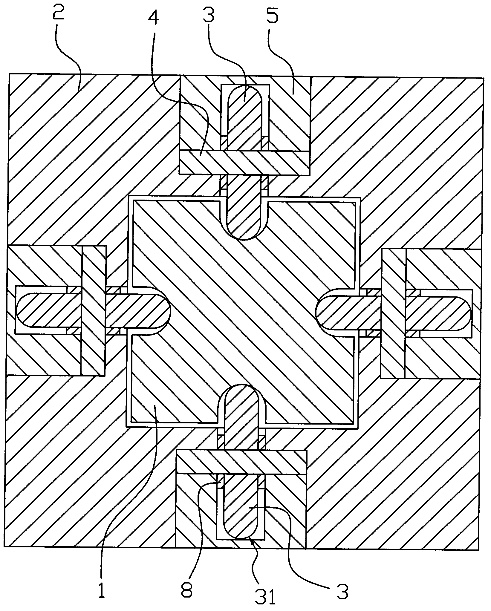
[0020] Example one, such as Figure 1 to Figure 4 As shown in the slide rail device of this embodiment, the sliding block 2 can be slidably placed on a matching guide rail 1. The guide rail 1 is a rectangular strip, and the middle of the four sides of the rectangular strip is provided with axial recesses. The two ends of the sliding groove 11 pass through, the orthographic projection of the end surface of the guide rail 1 is a rectangle with notches in the middle of the four sides, and the sliding block 2 is axially provided with a rectangular cavity 21 that penetrates through the two ends and is adapted to the rectangular strip. , And the four inner walls of the rectangular cavity 21 are respectively provided with rollers 3: the slider 2 is provided with a roller groove 22 and a shaft seat groove 23 on the four sides, and the roller 3 extends into the rectangular cavity 21 and corresponds to the sliding groove 11 can be fitted together in a rolling manner, and the roller 3 is e...

Embodiment 2

[0021] Example two, such as Figure 5 to Figure 8 As shown, the slide rail device of this embodiment is similar in structure to the above device. The specific structure of the roller 3 protruding on the inner wall of the rectangular cavity 21 is: the sliding block 2 is provided with module cavities 24 on all four sides, respectively. A suitable module 6 is inserted in the module cavity 24, and the roller 3 is rotatably arranged in the module 6. When the module 6 is inserted in the module cavity 24 of the slider 2, the roller 3 extends The inner wall of the rectangular cavity 21 and the corresponding sliding groove 11 can be fitted together in a rolling manner. The module 6 is fixed to the sliding block by a fastener 7. The fastener 7 may be a screw or a bolt.


PUM


Abstract

The invention discloses a sliding track device comprising a slider (2), wherein the slider (2) is mounted on a matching guide track (1) in a sliding manner. The sliding track device is characterized in that the guide track (1) is a rectangular strip, concave sliding chutes (11) are axially formed at the middle of the four sides of the rectangular strip respectively and the two ends of each concave sliding chutes are communicated, the end-face orthographic projection of the guide track (1) is a rectangle having notches at the middle of the four sides, a rectangular cavity (21) is axially formed within the slider (2), wherein the two end of the rectangular cavity are communicated and fits well with the rectangular strip, raised roller wheels (3) are formed on the inner walls of the four sides of the rectangular cavity (21) respectively, and when the slider (2) is mounted on the guide track (1), the roller wheels (3) raised from the inner walls of the four sides can roll in the corresponding sliding chutes (11). The sliding track device has the advantages that the design is smart, the stress points are increased and also distributed on the four sides of the guide track to ensure more uniform stress, and the guide track is enclosed within the rectangular cavity, so as to reduce the frictional force of the slider during movement and ensure that the movement of the slider is more stable and flexible.

Description

Technical field [0001] The invention relates to the technical field of sliding rail manufacturing, in particular to a sliding rail device. Background technique [0002] An existing Chinese utility model patent named "Linear Slider" with the patent number CN20112027928.6 discloses a linear slider, which includes a base, two circulators and more than two rollers. Plastic molding has a covering body. The covering body is provided with a load rail and a non-load rail for the roller to roll along the linear movement direction of the linear sliding block, and the covering body is on the outer side of the inner and outer sides of the base. Tension anchors are formed between the surface and the inner surface; the circulator includes an inner rail seat and an outer rail seat. The inner and outer rail seats are simply embedded and fixed on the outer side of the covering body at both ends of the base, so that the inner rail seat and the outer The rail seat matching group defines a circulat...

Claims


Application Information

Patent Timeline
Patent Type & Authority Applications(China)
IPC IPC(8): F16C29/04
Inventor 胡旭辉
Owner 邳州市承鼎机械设备有限公司
Why Eureka
Try Eureka