Gear shifter for gearshift transmissions

A technology for shifting transmissions and shifting devices, which is applied in the direction of transmission control, components with teeth, belts/chains/gears, etc., and can solve problems such as unallowable high surface pressure, so as to reduce surface pressure and reduce friction Effect

Active Publication Date: 2017-03-01
GETRAG FORD TRANSMISSIONS GMBH
View PDF1 Cites 0 Cited by
  • Summary
  • Abstract
  • Description
  • Claims
  • Application Information

AI Technical Summary

Problems solved by technology

If the locking element is designed as a ball with a small ball diameter, impermissibly high surface pressures result

Method used


Image

  • Gear shifter for gearshift transmissions
  • Gear shifter for gearshift transmissions

Examples


Embodiment Construction

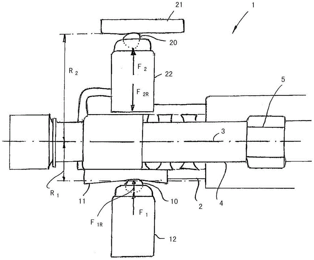
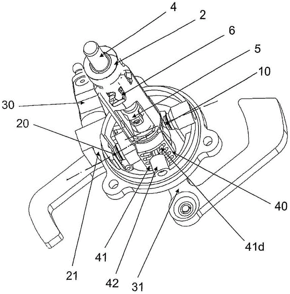
[0021] figure 1 A shifting device is shown, indicated in its entirety by 1 . Gears can be shifted in a gearshift transmission by means of the shifting device 1 . The shifting device 1 includes a shifting shaft 2 with a longitudinal axis 3 . The shift shaft 2 is displaceable along a longitudinal axis 3 . Furthermore, the selector shaft can also be rotated about the longitudinal axis in the circumferential direction. The gearshift shaft 2 is designed here as a tubular body arranged coaxially with an inner shaft 4 . A drive element 5 is non-rotatably connected to the inner shaft 4 , which connects the selector shaft 2 or the tubular body to the inner shaft 4 in a non-rotatable, but axially movable connection. The interaction of the shift shaft 2 and the inner shaft 4 will also be described later on.

[0022] A first locking element in the form of a ball 10 presses against a first locking contour 11 . In this case, the detent contour 11 is fixed on the shift shaft 2 , so tha...


PUM


Abstract

The switching device (1) has a shift shaft (2) which is rotatable in circumferential direction, along a longitudinal axis (3). A locking element (10) presses a locking contour (11) so that the shift shaft is held in axial detent position. A locking element (20) presses a locking contour (21) so that the shift shaft is held in circumferential detent position. The average effective radius of locking contour (21) and average effective radius of the locking contour (11) are different.

Description

technical field [0001] The invention relates to a shifting device for a shifted transmission, wherein the shifting device comprises a shifting shaft which is movable in the axial direction along a longitudinal axis and which is rotatable about the longitudinal axis in the circumferential direction. Background technique [0002] EP 1 036 962 B1 discloses a shifting device with a shifting shaft displaceable in the axial direction and rotatable in the circumferential direction. A first locking element and a first locking contour interact in such a way that the first locking element, which is pressed against the first locking contour by a first force, ensures the axial locking position of the shift shaft. . In addition, a second locking element and a second locking contour are provided, wherein a second force in the form of a spring force presses the second locking element against the second locking contour and thus holds the selector shaft on the circumference direction in at...

Claims


Application Information

Patent Timeline
Patent Type & Authority Patents(China)
IPC IPC(8): F16H63/34F16H63/38
Inventor A·哈里里
Owner GETRAG FORD TRANSMISSIONS GMBH
Why Eureka
Try Eureka