Vehicle seat

a technology for vehicles and seats, applied in the field of vehicles, can solve problems such as the difficulty of rotating the headrest without fail, and achieve the effect of reducing the pressure on the surfa

Active Publication Date: 2010-03-09
NHK SPRING CO LTD +1
View PDF13 Cites 13 Cited by
  • Summary
  • Abstract
  • Description
  • Claims
  • Application Information

AI Technical Summary

Benefits of technology

[0011]Accordingly, in the first aspect of the vehicle seat, both of the two legs are moved by combination movement of the second interacting member with the first interacting member. The pair of legs surely move without entanglement, and thus, displacement of the headrest displaces toward the front is ensured.
[0035]In the vehicle seat according to the seventh aspect, surface pressure can be reduced between the slider and the guide surface of the slider guide. Accordingly, against the load any one of the slider and the slider guide applies to the other, the other can bear the load even when mechanical strength thereof is not especially high.

Problems solved by technology

However, when a mechanism of the active headrest constituted so as to pull the headrest vertical adjustment mechanism by the wire is applied to a headrest that is attached on the seat back by a pair of legs, without applying even rotation force through a wire tension to the two legs, it is difficult to rotate the headrest without fail because of entanglement of the movement.

Method used


Image

  • Vehicle seat
  • Vehicle seat
  • Vehicle seat

Examples


first embodiment

1. First Embodiment

[0050]10>

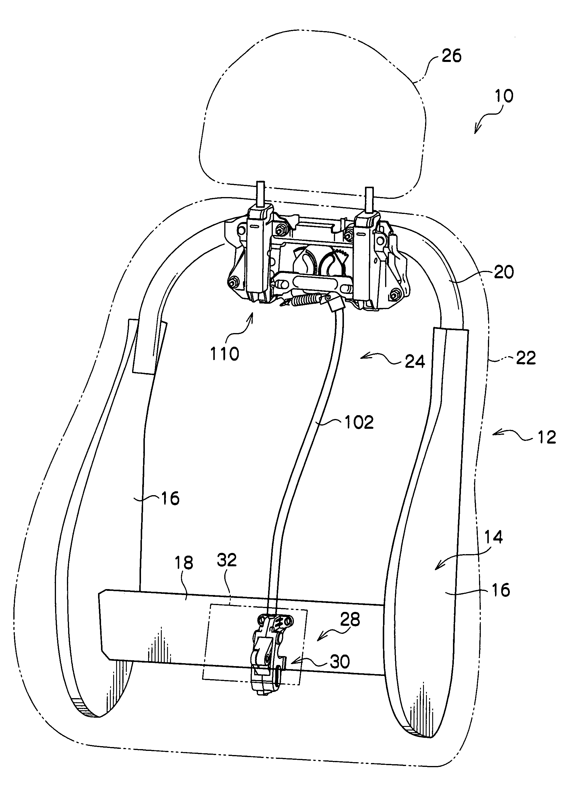
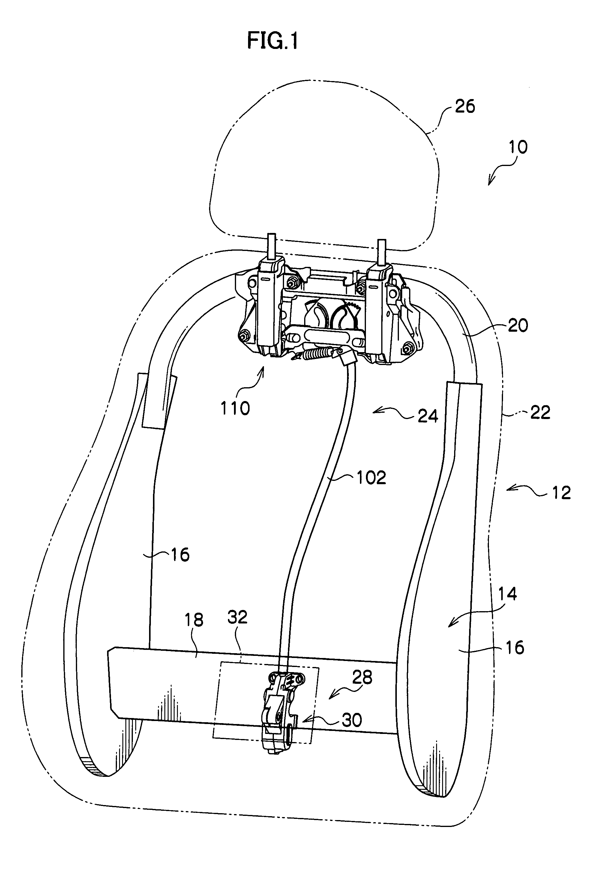
[0051]FIG. 1 shows a perspective view of an essential-part structure of a vehicle seat 10 according to a first embodiment of the present invention.

[0052]As shown in the FIG. 1, the vehicle seat 10 has a seat back 12 constituting a seat body. The seat back 12 has a seat-back frame 14 making up a skeleton member for the seat back 12. The seat-back frame 14 has a pair of side frames 16. Each of the side frames 16 is formed as a plate having a thickness thereof arranged in the widthwise of the vehicle seat 10, and disposed so as to face each other in the widthwise of the vehicle seat 10.

[0053]A lower frame 18 is provided between lower ends of the side frames 16. The lower frame 18 is formed as a plate having a thickness thereof basically arranged in the thickness direction of the vehicle seat 10. The lower frame 18 has one end fixed to one of the side frames 16 and the other end to the other of the side frames 16. Due to this, the both side frames 16 are conn...

second embodiment

2. Second Embodiment

[0113]Now a modification of the detector body 30 is described as a second embodiment. Incidentally, in the second embodiment, reference numerals that are identical with those in the first embodiment show the identical element.

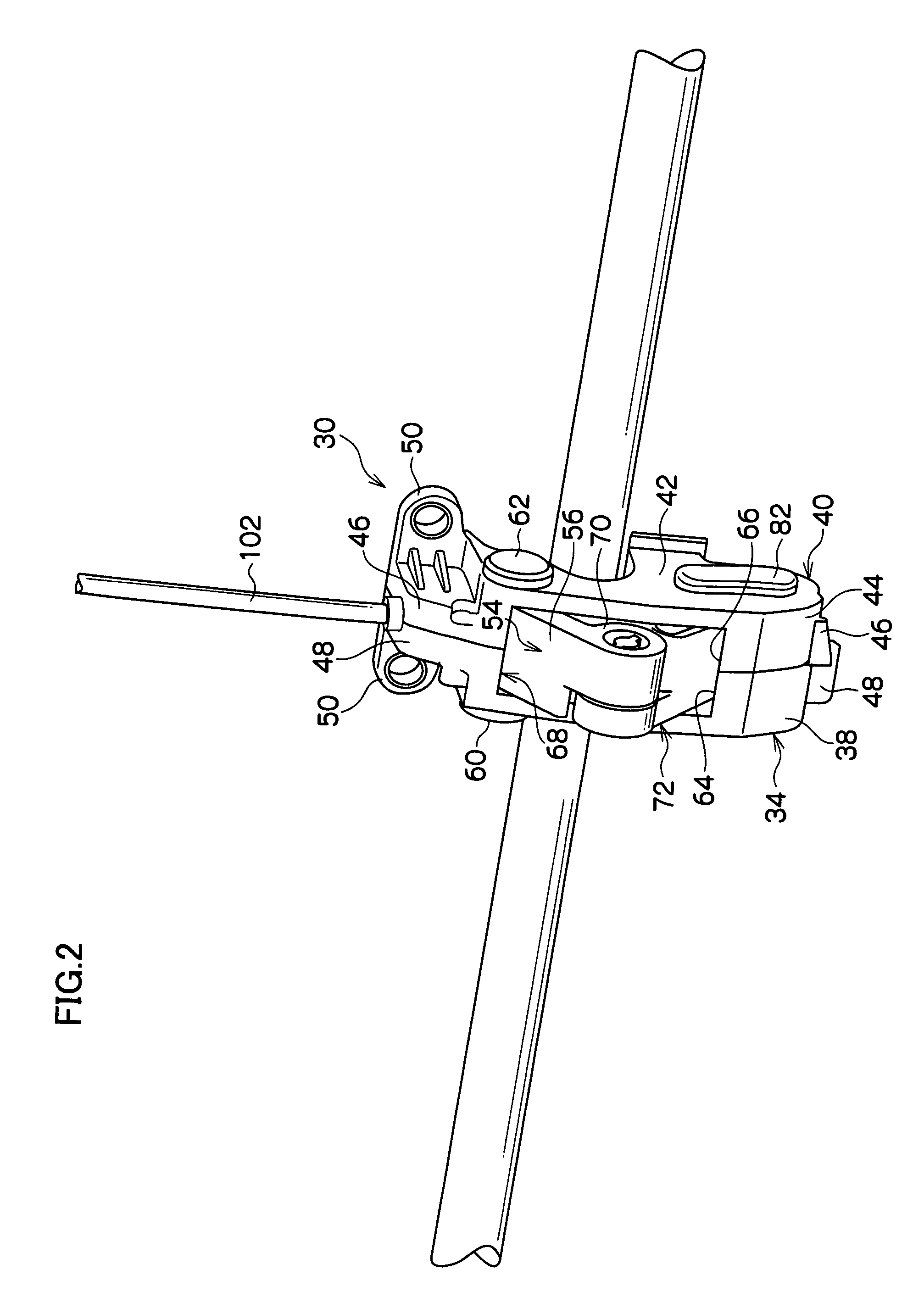
[0114]FIG. 13 shows an exploded perspective view of a detector body 172 structure of a load detector 170 that corresponds to the load detecting means of the present invention and is a modification of the detector body 30 of the load detector 28. As shown in the figure, the detector body 172 has substantially identical structure with the detector body 30. However, in the detector body 30, one end of the cable 98 engages with the slide shaft 78 through the plate 100, on the other hand, in the detector body 172, the cable 98 is wrapped around the slide shaft 78, bent back, and fixed in the leftward housing 40 at a portion closer to the shaft 58 than the slide shaft 78.

[0115]Consequently, in the detector body 172, when the slide shaft 78 is guid...


PUM


Abstract

A vehicle seat includes a seat body having a seat back, a pair of left and right legs, a headrest coupled to the seat back at above the seat back through the pair of legs, load detecting means provided on the seat back and having a movable part that displaces in a predetermined direction upon undergoing a load from the front of the seat back; a first interacting member mechanically coupled to one leg of the pair and to the movable part of the load detecting means, to move one leg of the pair in conjunction with a displacement of the movable part caused upon undergoing the load, thereby displacing the headrest frontward, and a second interacting member mechanically coupled to the other leg of the pair and to the first interacting member, to move the other leg of the pair in conjunction with a movement of the first interacting member caused upon moving the one leg of the pair, thereby displacing the headrest frontward.

Description

CROSS-REFERENCE TO RELATED APPLICATION[0001]This application claims priority under 35 USC 119 from Japanese Patent application No. 2006-189467, the disclosure of which is incorporated by reference herein.BACKGROUND OF THE PRESENT INVENTION[0002]1. Field of the Present Invention[0003]The present invention relates to a vehicle seat to be mounted on a vehicle.[0004]2. Description of the Related Art[0005]For example, JP-A-2005-212596 discloses an example of so-called an “active headrest” arranged such that, in the event of a collision of a vehicle from behind, the headrest is moved toward the front of the vehicle in order to narrow the spacing between the passenger's head and the headrest.[0006]In the active headrest described in this publication, a lumbar support mechanism is supported rotatably about the axis extending left and right inside of the seat back wherein the lumbar support mechanism is urged toward the front by means of a spring. When the passenger is suddenly moved rearwar...

Claims


Application Information

Patent Timeline
Patent Type & Authority Patents(United States)
IPC IPC(8): B60N2/42
CPCB60N2/4808B60N2/4838B60N2/4885B60N2/838B60N2/809B60N2/888
Inventor YAMAGUCHI, HIROYOSHIHASEGAWA, MAKOTOOHCHI, MASATOTANINO, MASAHARUSUZUKI, SHINJI
Owner NHK SPRING CO LTD
Why Eureka
Try Eureka