High-frequency clock duty-ratio test circuit
A technology of duty ratio and comparison circuit, which is applied in the direction of monitoring pulse chain mode, etc., and can solve the problems of reducing clock frequency, clock duty ratio test, interference, etc.
- Summary
- Abstract
- Description
- Claims
- Application Information
AI Technical Summary
Problems solved by technology
Method used
Image
Examples
Embodiment Construction
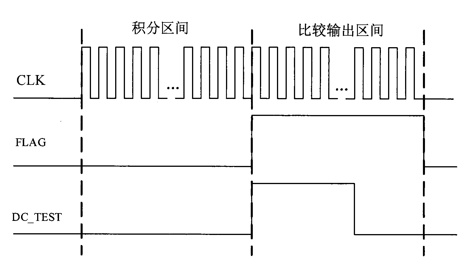
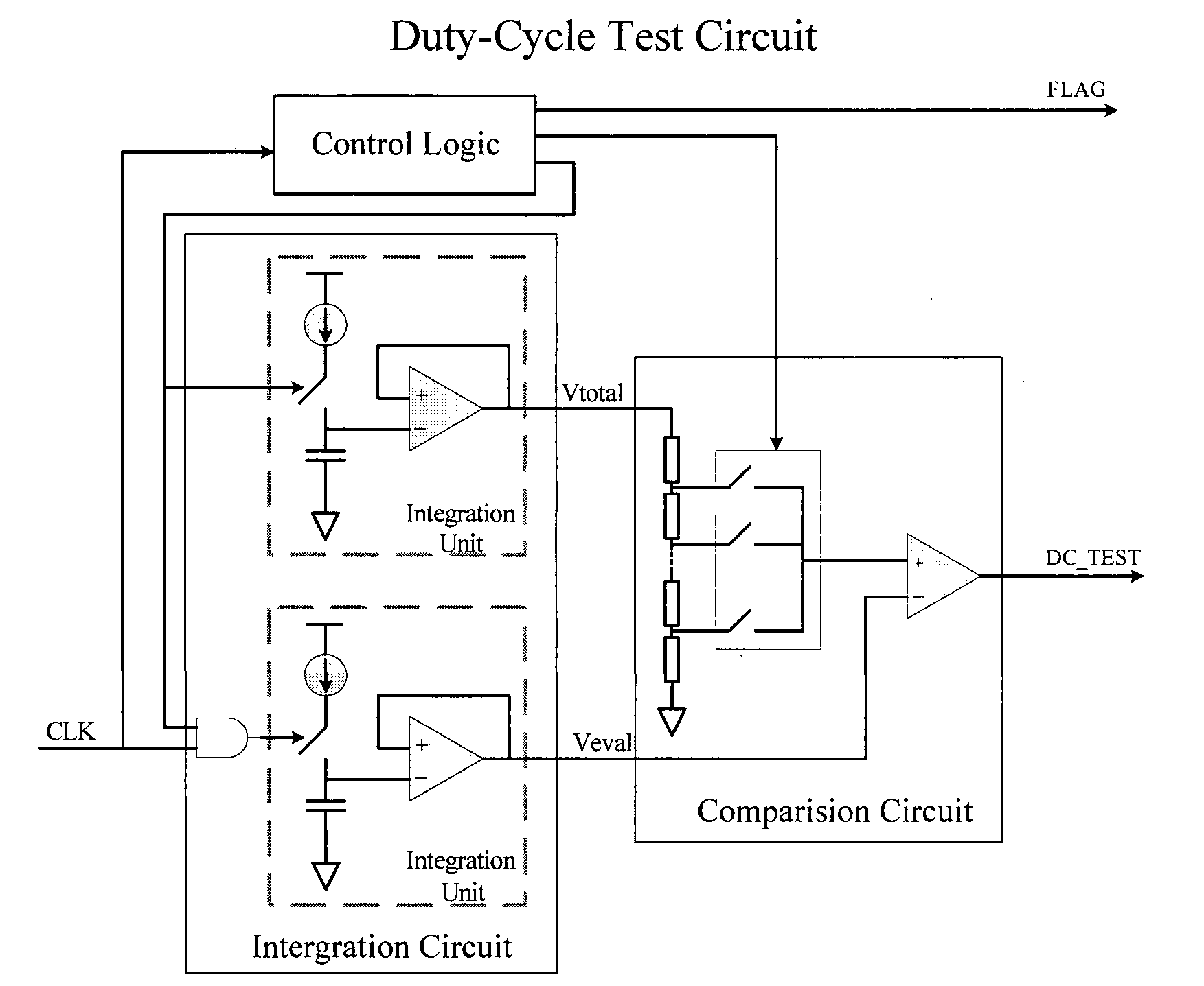
[0016] The circuit implementation structure is specifically introduced below in conjunction with the accompanying drawings, such as image 3 shown. The waveform diagram of each node inside the circuit, such as Figure 4 shown.
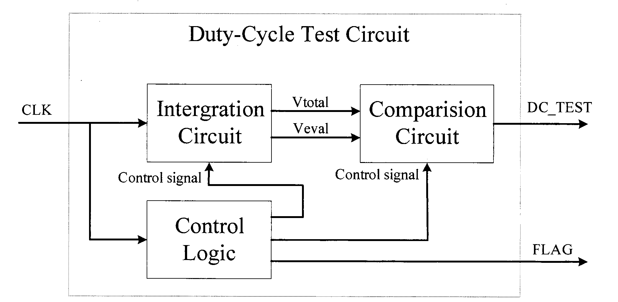
[0017] The integral circuit is controlled by the counter inside the control logic, and integrates within N clock cycles. The integral unit is composed of a switched capacitor charge and discharge circuit and a source follower circuit. The source follower circuit makes the integral output voltage have a certain current drive capability to divide the voltage. Generate the reference voltage required by the comparison circuit. The control circuit outputs a signal CON representing the integration interval, and CON is used as an input of an integration unit to generate a reference voltage Vtotal. The AND of the integration interval signal CON and the clock signal CLK is used as an input of another integration unit to generate an evaluation voltage Veval. ...
PUM
 Abstract
Description
Claims
Application Information
 - R&D
- Intellectual Property
- Life Sciences
- Materials
- Tech Scout
- Unparalleled Data Quality
- Higher Quality Content
- 60% Fewer Hallucinations
Browse by: Latest US Patents, China's latest patents, Technical Efficacy Thesaurus, Application Domain, Technology Topic, Popular Technical Reports.
© 2025 PatSnap. All rights reserved.Legal|Privacy policy|Modern Slavery Act Transparency Statement|Sitemap|About US| Contact US: help@patsnap.com


