High frequency clock duty ratio test circuit

A technology for testing circuits and high-frequency clocks, applied in the monitoring pulse chain mode and other directions, which can solve problems such as clock duty cycle testing, interference, and affecting the accuracy of test results.

Inactive Publication Date: 2014-03-26
BEIJING CEC HUADA ELECTRONIC DESIGN CO LTD
View PDF3 Cites 6 Cited by
  • Summary
  • Abstract
  • Description
  • Claims
  • Application Information

AI Technical Summary

Problems solved by technology

In order to prevent the distortion of the clock waveform and affect the accuracy of the test results, the duty ratio test has high requirements on the IO drive capability, but if the IO drive capability is too large, it will cause interference to other circuits under the same power system.
If the high-frequency clock uses digital frequency division to reduce the clock frequency, the clock duty cycle cannot be tested after frequency division

Method used


Image

  • High frequency clock duty ratio test circuit
  • High frequency clock duty ratio test circuit
  • High frequency clock duty ratio test circuit

Examples


Embodiment Construction

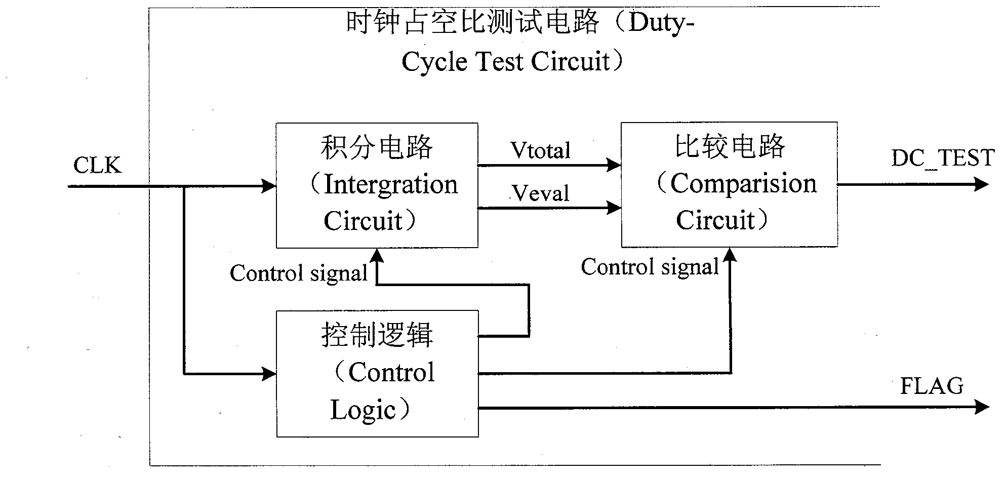
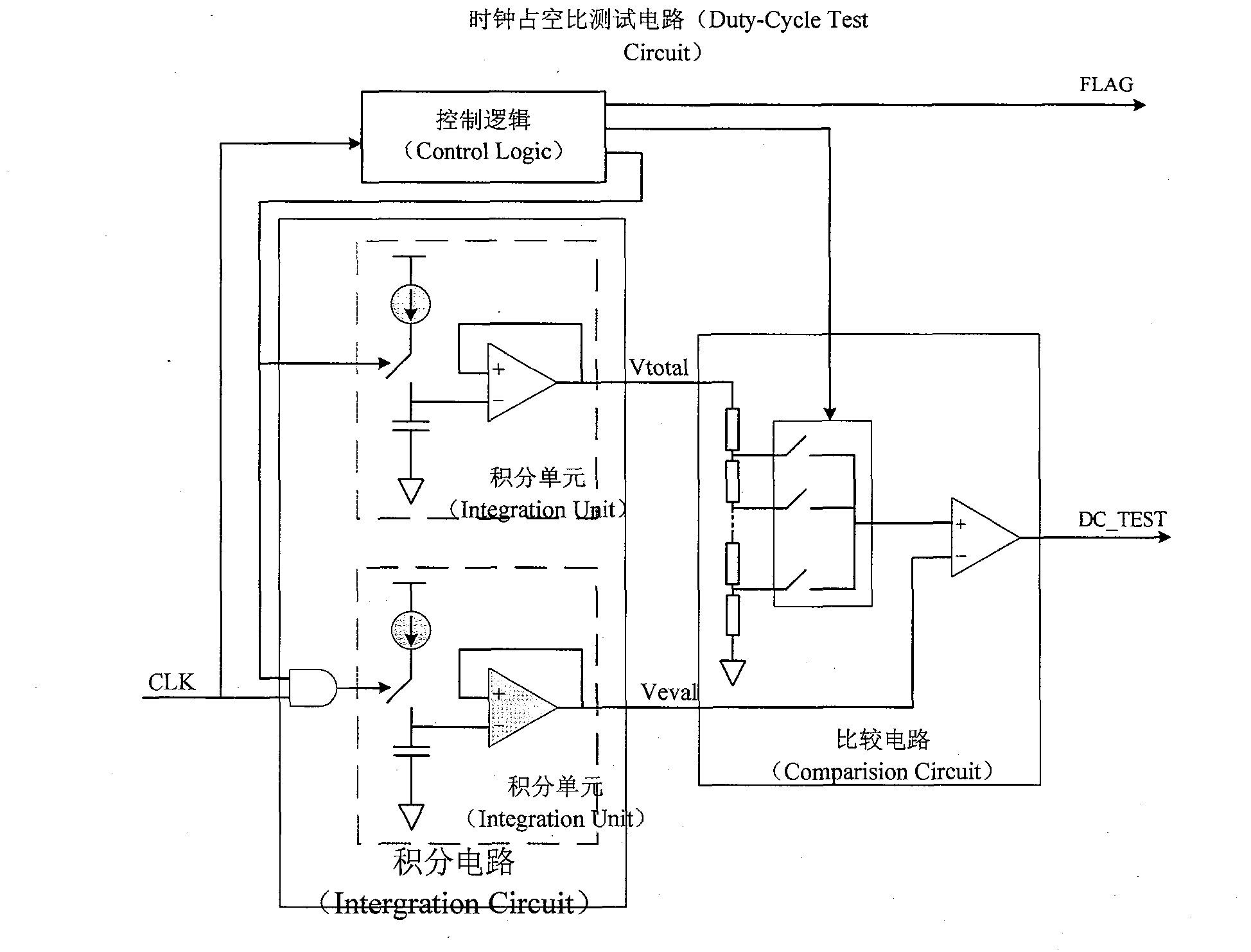
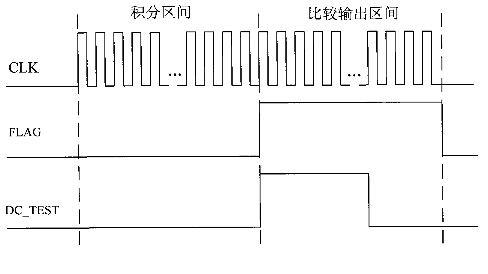
[0016] The circuit implementation structure is specifically introduced below in conjunction with the accompanying drawings, such as image 3 shown. The waveform diagram of each node inside the circuit, such as Figure 4 shown.

[0017] The integral circuit is controlled by the counter inside the control logic, and integrates within N clock cycles. The integral unit is composed of a switched capacitor charge and discharge circuit and a source follower circuit. The source follower circuit makes the integral output voltage have a certain current drive capability to divide the voltage. Generate the reference voltage required by the comparison circuit. The control circuit outputs a signal CON representing the integration interval, and CON is used as an input of an integration unit to generate a reference voltage Vtotal. The AND of the integration interval signal CON and the clock signal CLK is used as an input of another integration unit to generate an evaluation voltage Veval. ...


PUM


Abstract

The invention provides a high frequency clock duty ratio test circuit. By using a switch capacitor structure, time quantity is converted into voltage quantity. Through voltage quantitative comparison, equal proportion amplification is carried out on high and low level time of a clock, and an accurate test is carried out on the duty ratio of a high frequency clock signal. The test precision of the duty ratio does not depend on an implementation process, but simply depends on the design precision.

Description

Technical field: [0001] The invention relates to a test circuit for the duty ratio of a high-frequency clock, which uses a switched capacitor structure to convert the amount of time into a voltage amount, and amplifies the high and low level time of the clock in equal proportions through quantitative comparison of the voltage, so as to realize the performance of the duty ratio of the high-frequency clock The accurate test can be used for the clock double-edge working system test to evaluate the clock duty cycle. Background technique: [0002] On-chip clock generation circuits, such as phase-locked loops, frequency synthesizers, oscillators, etc., are widely used in various chips to provide clocks for digital circuit work and timing for data transmission of communication interfaces. In order to improve the working speed of the chip, some applications use clock double edge to work. In order to ensure the correctness of the timing, certain constraints are put forward on the du...

Claims


Application Information

Patent Timeline
Patent Type & Authority Applications(China)
IPC IPC(8): H03K5/19
Inventor 高慧
Owner BEIJING CEC HUADA ELECTRONIC DESIGN CO LTD
Why Eureka
Try Eureka