
Prosthetic foot

A prosthetic foot and heel technology, applied in prosthesis, medical science, artificial legs, etc., can solve problems that are not conducive to the accuracy of force introduction, small reset force, etc., and achieve the effect of accurate support point and long-lasting position

Active Publication Date: 2013-07-03
OTTO BOCK HEALTHCARE IP GMBH & CO KG
View PDF10 Cites 3 Cited by
  • Summary
  • Abstract
  • Description
  • Claims
  • Application Information

AI Technical Summary

Problems solved by technology

However, only small restoring forces can be achieved with the elastic plastic cylinder, so that the elastic properties of the artificial foot must be realized only through the plantar structure when walking
Furthermore, the use of wear-prone elements via plastic cylinders impairs the precise force introduction

Method used


Image

  • Prosthetic foot
  • Prosthetic foot
  • Prosthetic foot

Examples


Embodiment Construction

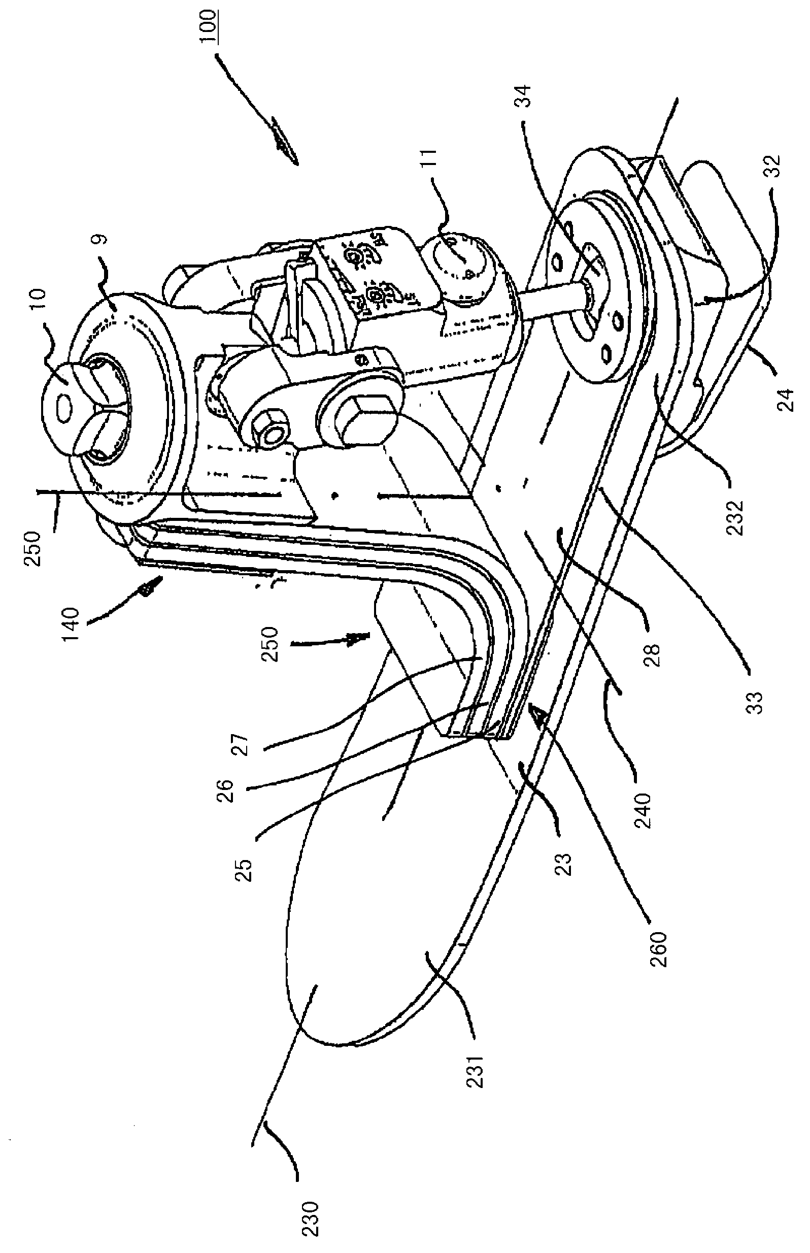
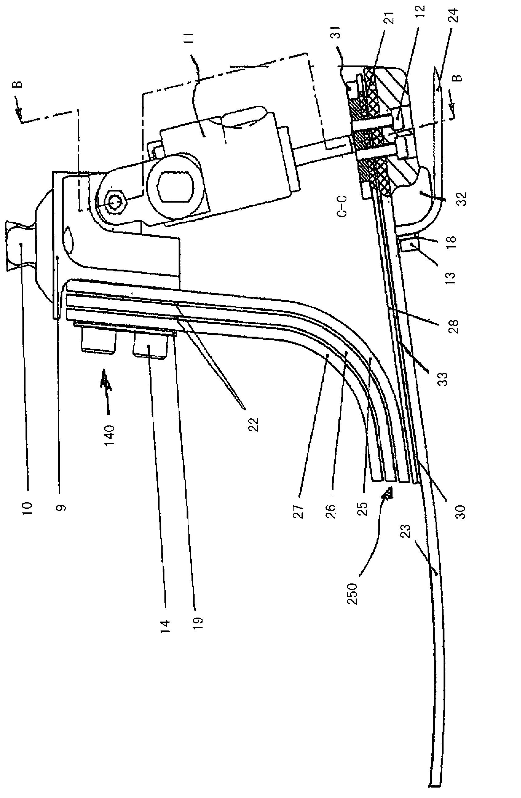
[0026] exist figure 1The prosthetic foot 100 is shown in a three-dimensional oblique top view. The prosthetic foot 100 has a base spring 23 with a forefoot region 231 and a heel region 232 . The base spring 23 is preferably produced from a fiber composite material, in particular from a carbon fiber component. The base spring 23 is elongated, wherein the prosthetic foot longitudinal axis 230 extends in the longitudinal direction. The base spring 23 is substantially straight, with a slight bend provided in the forefoot region 231 to facilitate rolling over of the prosthetic foot 100 .

[0027] A heel spring 24 is arranged on the base spring 23 in the heel region 232 . The heel spring 24 is likewise made of a fiber composite material, in particular a carbon fiber material. The heel spring 24 can be fixed exchangeably on the base spring 23 . Between the heel spring 24 and the base spring 23 there is a free space which contracts in the direction of travel, in which free space ...


PUM


Abstract

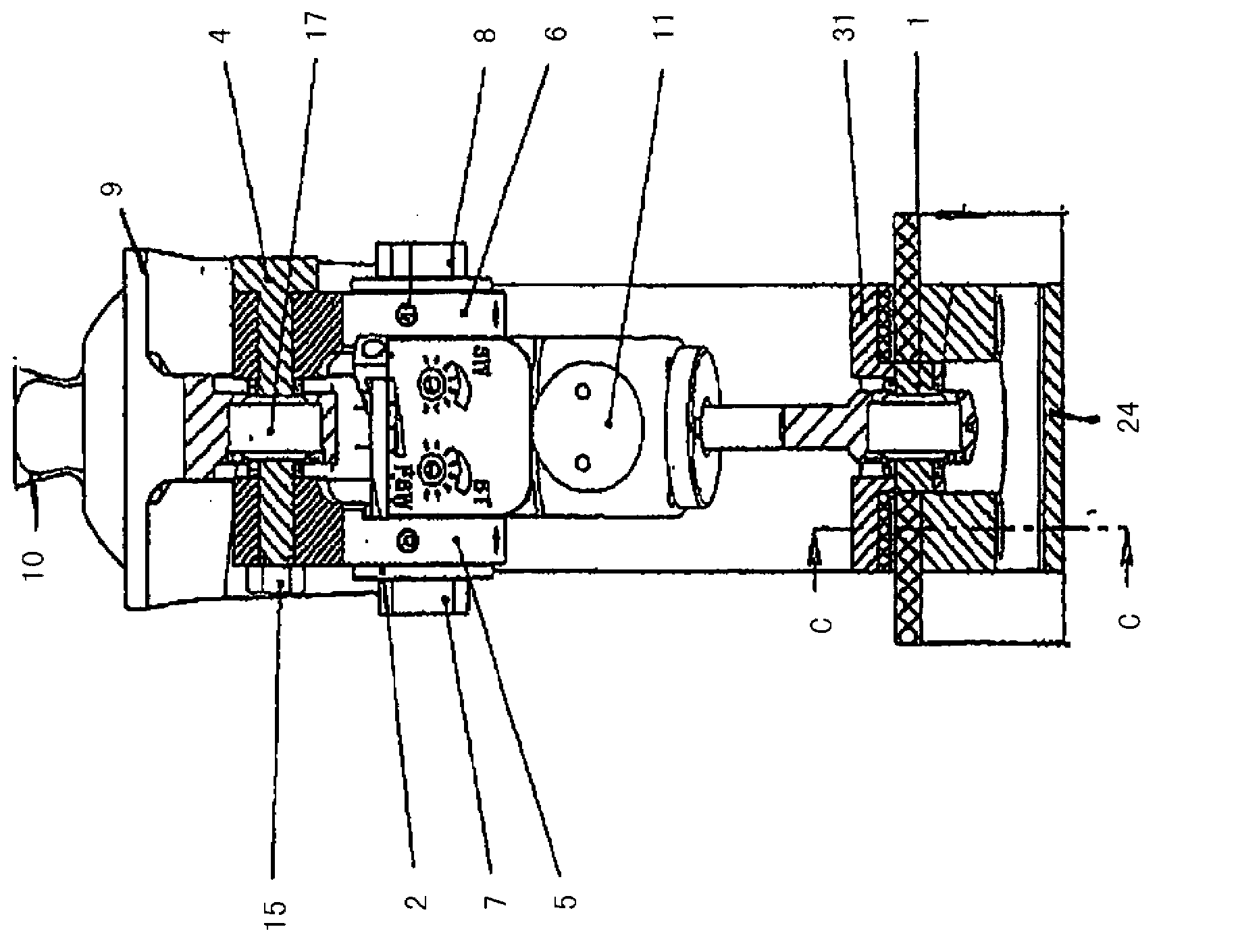
The invention relates to a prosthetic foot with a base spring (23) with a forefoot area (231) and a heel area (232), a connecting means (9, 10) arranged above the base spring (23) and used to fasten the prosthetic foot to a prosthesis, and a frontal support (25, 26, 27), at the upper end (140) of which the connecting means (9, 10) is arranged and which, at its lower end (250), is secured on a torsion element (28) that can twist about the longitudinal axis (230) of the prosthetic foot, wherein the torsion element (28) is designed as a leaf spring arrangement secured to the base spring (23) at one end in the heel area (232) or in the forefoot area (231).

Description

technical field [0001] The invention relates to a prosthetic foot having a basic body spring with a forefoot region and a heel region, the prosthetic foot also having a connecting device arranged above the basic body spring for fastening the prosthetic foot to the prosthesis, and having A front support device, on whose upper end the connection device is arranged and on whose lower end a torsion element is fastened which can be rotated about the longitudinal axis of the prosthetic foot. The invention likewise relates to a prosthetic foot having a base spring with a forefoot region and a heel region, the prosthetic foot also having a connecting device arranged above the base spring for fastening the prosthesis to the prosthesis. Background technique [0002] DE 10 2006 004 132 A1 describes an artificial foot with an elastic plantar structure extending from the heel area to the toe area, the plantar structure has a longitudinal axis, connection means to the lower leg, height-ex...

Claims


Application Information

Patent Timeline
Patent Type & Authority Applications(China)
IPC IPC(8): A61F2/66
CPCA61F2/66A61F2002/5006A61F2002/5007A61F2002/6657A61F2002/6678
Inventor L·莫斯勒
Owner OTTO BOCK HEALTHCARE IP GMBH & CO KG
Learn More