Device for controlling pivoting blades of a turbine engine

A technology for control devices and turbines, which is applied to parts of pumping devices for elastic fluids, mechanical equipment, engine components, etc., can solve problems such as positioning and centering restrictions, high stress on control devices, and device uncertainty, etc., to achieve Improvement of reliability, improvement of performance, effects that can be improved

Active Publication Date: 2013-07-03
TURBOMECA SA
View PDF6 Cites 8 Cited by
  • Summary
  • Abstract
  • Description
  • Claims
  • Application Information

AI Technical Summary

Problems solved by technology

The action of this type of device is very complex and very precise, such that if the precision clearances are not met, the device will be statically indeterminate (i.e. it will jam)
In particular, this means that the positioning and centering of the ring sections with respect to the turbine axis is severely restricted
For this reason, even slight deviations from these positions can quickly cause very high stresses on the entire control unit, which in turn can cause it to jam
This centering (or, more generally, positioning) problem is further exacerbated by differences in thermal expansion between the various parts of the control

Method used


Image

  • Device for controlling pivoting blades of a turbine engine
  • Device for controlling pivoting blades of a turbine engine
  • Device for controlling pivoting blades of a turbine engine

Examples


Embodiment Construction

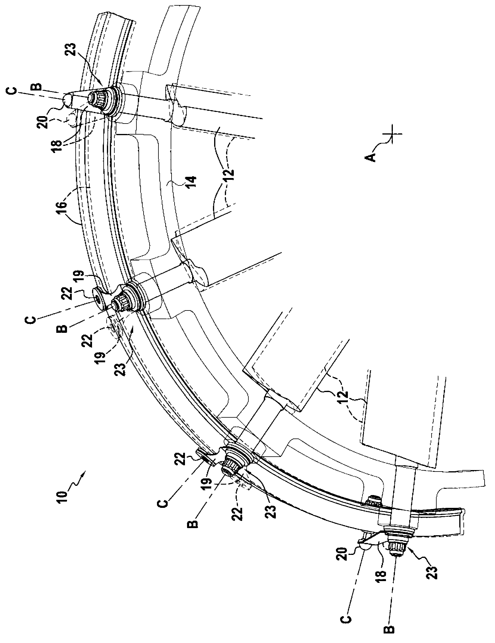
[0038] figure 1 An embodiment of the control device of the invention for controlling pivoting blades of a turbomachine is shown. In this embodiment, the blades are oriented radially with respect to the turbine axis. The schematic diagram shown is a partial one, the whole arrangement extending 360° around the axis A of the turbine (not shown). This axis A forms the longitudinal direction. The radial and azimuthal directions are determined with respect to the axis A.

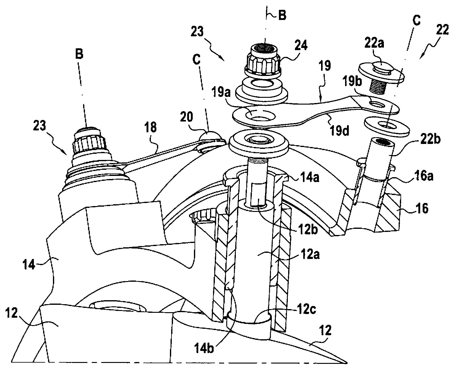
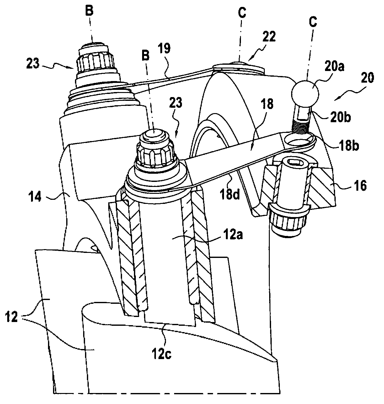
[0039] The control unit 10 includes a plurality of vanes 12 pivotally mounted on a stator 14 . The pivot axis B of each blade 12 is oriented in a radial direction. Each blade 12 is mounted on the stator 14 by a pivot-only connection 23 (ie pivot connection) in which the only movement (or degree of freedom) allowed is a rotational movement about the axis B.

[0040] Each blade 12 is connected to a control ring 16 by a connecting rod. Each rigid link 18 connects the blade 12 to the control ring 16 by a ball jo...


PUM


Abstract

The invention relates to a device (10) for controlling pivoting blades of a turbine engine, including a plurality of pivoting blades (12) that are azimuthally distributed over at least 90 about the axis (A) of the turbine engine, said pivoting blades (12) being substantially radially oriented relative to the axis (A) of the turbine engine; and a control ring portion (16) for controlling the pivoting of the blades (12), each blade (12) being connected to the control ring portion (16) by a connecting rod (18, 19). The control ring portion (16) is supported about the axis (A) of the turbine engine by the set of connecting rods (18, 19), wherein at least two connecting rods (18) are connected to the ring portion by a ball-joint connection (20), and the other connecting rods (19) are connected to the ring portion by a sliding pivot connection (22).

Description

technical field [0001] The present invention relates to an apparatus for controlling the pivoting vanes of a turbomachine, and in particular, to an apparatus for controlling the pivoting vanes in a synchronized manner. Background technique [0002] On turbines, it is known to employ one or more stages of stator blades to adjust the airflow and the direction of gas flow through the compression section according to the speed at which the turbine is operating. These stator blade stages include a plurality of blades (also known as variable pitch blades) that are pivotable about an axis connecting them to the stator so that their pitch angle can be modified according to the speed at which the turbine is operating. [0003] Known means for controlling the pivoting vanes of a turbine generally comprise a plurality of pivotable vanes azimuthally distributed at an angle of at least 90° about the axis of the turbine, the pivotable vanes being oriented generally radially with respect t...

Claims


Application Information

Patent Timeline
Patent Type & Authority Applications(China)
IPC IPC(8): F01D17/16
CPCF01D17/162Y02T50/60F01D17/16F05D2220/40Y02T10/12F04D29/563
Inventor 克里斯托弗·科莱特伯纳德·利安娜
Owner TURBOMECA SA
Why Eureka
Try Eureka