Gravity drainage system for underground roadway high-pressure water inrush

A self-flowing drainage and underground roadway technology, which is applied to drainage, safety devices, mining equipment, etc., can solve problems such as consuming manpower and material resources, wasting electric energy, and complex construction techniques

Inactive Publication Date: 2013-07-10
CHINA UNIV OF MINING & TECH
View PDF5 Cites 13 Cited by
  • Summary
  • Abstract
  • Description
  • Claims
  • Application Information

AI Technical Summary

Problems solved by technology

Although the above methods are active protection methods, they all have complex construction techniques, long construction periods, high costs, and tens of millions of dollars. Sometimes, if the design of parameters such as drilling positions and depths is inaccurate, and the location of water inrush channels is judged incorrectly, it is easy to cause closures. Block failure
At present, direct forced drainage in the roadway is the third response method, but this method is a passive protection method. Sometimes for the sake of safety, temporary retaining walls are also built for grouting or temporary water retaining. They are

Method used


Image

  • Gravity drainage system for underground roadway high-pressure water inrush
  • Gravity drainage system for underground roadway high-pressure water inrush
  • Gravity drainage system for underground roadway high-pressure water inrush

Examples


Embodiment Construction

[0023] The present invention will be further described below in conjunction with accompanying drawing.

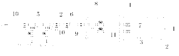
[0024] Such as figure 1 As shown, a water retaining wall 1 is built in the roadway 3 between the anti-water barrier gate 8 and the water gushing point 2. The roadway 3 is preferably reinforced by grouting and sprayed anchors. The water retaining wall 1 is made of steel bars, cement 1. Sand and stone masonry, with a thickness of not less than 3m, so that it can withstand not less than 3 times the hydrostatic pressure of the water storage space 4, and the two sides are embedded in the roadway 3 wall to a depth of at least 50cm, and the combination is tight. The masonry site should be selected in There is a certain safe distance from the water outlet point and the surrounding rock of the roadway 3 is stable. During construction, the original water pump drainage work needs to be continued to maintain the normal construction of the cutoff wall. After the completion, stop the pu...


PUM


Abstract

The invention discloses a gravity drainage system for underground roadway high-pressure water inrush. A retention wall is built in a roadway between a waterproof gate and an inrush point, and the roadway and the retention wall form a water storage space. The retention wall is provided with at least one drain pipe connected with the water storage space and space outside the retention wall. The drain pipes lead to a mining horizontal central water sump, an upper horizontal central water sump or the ground. The gravity drainage system for underground roadway high-pressure water inrush has the advantages that the cost is low, the structure is simple, no electricity is needed, drainage equipment is used less frequently or no drain pump is used, continuous drainage is facilitated and insusceptible to electricity, water resources are protected, sewage treatment cost is lowered, water release can be controlled through a valve, sampling is available anytime, the analysis on changing of the recharge water is assisted, and considerable water is provided for mine production.

Description

technical field [0001] The invention relates to a drainage system for a mine, in particular to an artesian drainage system for highly pressured water gushing in an underground roadway. Background technique [0002] It is a difficult problem to eliminate the water gushing in the underground roadway with sufficient water supply, especially the floor water in highly pressurized mines. At present, three methods are adopted to deal with it. The first is to block the water outlet point by ground grouting, such as Figure 5 As shown, a series of boreholes are drilled on the ground above the water outlet point, drilled into the water inrush channel (usually a fault) around the water outlet point, and the water outlet point is blocked by injecting cement, sand aggregate or chemical materials; The second is downhole grouting to block the water outlet, such as Figure 6 As shown, that is, the water retaining wall is built first, and the water outlet point is blocked by grouting throu...

Claims


Application Information

Patent Timeline
IPC IPC(8): E21F16/00
Inventor 齐跃明罗斌赵小二巩萍马少莲罗蒙浪陈玉华董贵明张新霞杭远
Owner CHINA UNIV OF MINING & TECH
Why Eureka
Try Eureka