
Replenishing valve for hydraulic system of press

A technology of hydraulic system and filling valve, which is applied in the directions of fluid pressure actuating system components, mechanical equipment, fluid pressure actuating devices, etc. use, etc.

Inactive Publication Date: 2013-07-10
ANHUI KEDA IND CO LTD
View PDF7 Cites 1 Cited by
  • Summary
  • Abstract
  • Description
  • Claims
  • Application Information

AI Technical Summary

Problems solved by technology

[0002] The fully automatic two-way hydraulic brick machine has two upper and lower main oil cylinders. The pressing work of wall material products is completed under the cooperation of the upper and lower main oil cylinders. The upper and lower main oil cylinders are each equipped with a liquid filling valve to control the upper and lower main oil cylinders. The oil flows quickly during fast movement. In the fully automatic two-way hydraulic brick press, the installation of the lower filling valve is more difficult. Firstly, due to the limitation of the lower beam structure, the split type filling valve cannot be used; secondly, due to the lower beam Due to the limitation of structural strength and rigidity, the diameter of the hole in the lower beam for oil flow should not be too large. The traditional integrated filling valve structure occupies a large volume, and the oil flow is limited during rapid flushing.

Method used


Image

  • Replenishing valve for hydraulic system of press

Examples


Embodiment Construction

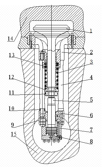
[0010] Referring to the accompanying drawings, a liquid filling valve for the hydraulic system of a press is installed on the bottom cover of the lower main oil cylinder and is located inside the main oil cylinder 14, including a valve core 1, a valve seat 2, a valve core control body, a connecting rod 4, and a return spring 3. Lock nut 11, spring gland 12 and guide sleeve 13, the return spring is fixedly arranged in the valve seat through the spring gland, the valve core extends into the return spring through the guide sleeve, and the valve core control body passes through the connecting rod and The lock nut is connected with the valve seat.

[0011] The valve core control body includes a control valve piston 5, a flange seat 6, a control valve cylinder 7, and a control valve cylinder cover 8. The control valve piston is connected with the valve core through a lock nut, and extends into the valve core through the flange seat. Control valve oil cylinder, the lower end of the c...


PUM


Abstract

The invention discloses a replenishing valve for a hydraulic system of a press. The replenishing valve comprises a valve spool, a valve seat, a valve spool control body, a connecting rod, a return spring, a locking nut, a spring pressing cover and a guide sleeve. The replenishing valve is characterized in that the return spring is fixedly arranged in the valve seat through the spring pressing cover, the valve spool extends into the return spring through the guide sleeve, and the valve spool control body is connected with the valve seat through the connecting rod and the locking nut. The replenishing valve is simple in structure, convenient to assemble and disassemble and large in through-flow area.

Description

technical field [0001] The invention belongs to an auxiliary device of a brick press, in particular to a liquid filling valve of a hydraulic system of a press. Background technique [0002] The fully automatic two-way hydraulic brick machine has two upper and lower main oil cylinders. The pressing work of wall material products is completed under the cooperation of the upper and lower main oil cylinders. The upper and lower main oil cylinders are each equipped with a liquid filling valve to control the upper and lower main oil cylinders. The oil flows quickly during fast movement. In the fully automatic two-way hydraulic brick press, the installation of the lower filling valve is more difficult. Firstly, due to the limitation of the lower beam structure, the split type filling valve cannot be used; secondly, due to the lower beam Due to the limitation of structural strength and rigidity, the diameter of the hole in the lower beam for oil flow should not be too large. The...

Claims


Application Information

Patent Timeline
Patent Type & Authority Applications(China)
IPC IPC(8): F15B21/00
Inventor 刘永生薛建华古小庆庞亮钱道光
Owner ANHUI KEDA IND CO LTD
Learn More