Multipurpose joint base

A joint seat and mandrel technology, applied in the direction of wrench, screwdriver, manufacturing tools, etc., can solve the problems of inconvenient use, complex structure, high processing cost, etc., and achieve the effect of accurate positioning and convenient use

Active Publication Date: 2013-07-17
美事满工具(海安)有限公司
11 Cites 3 Cited by

AI-Extracted Technical Summary

Problems solved by technology

[0002] The existing joint seat controls the movement of the first sphere through the cooperation of the outer sleeve and the rear sl...

Method used

Also be provided with handle 4, handle 4 is fixedly set on the outer side of mandrel 1 other end, mandrel 1 other end can also form hexagonal prism structure, and this hexagonal prism is provided with annular inner groove, and thi...

Abstract

The invention discloses a multipurpose joint base. The multipurpose joint base comprises a core shaft and a first sphere body, wherein an axial mounting groove for inserting a workpiece is sequentially arranged at the inner side from one end to the other end of the core shaft; the core shaft is provided with at least one radial first hole; the first hole is used for communicating the mounting groove in the core shaft with the outer side of the core shaft; the sphere body is placed in the first hole; one side, close to the core shaft mounting groove, of the sphere body can partially extend into the mounting groove and does not fall off; the multipurpose joint base is further provided with a first elastic piece; the first elastic piece is axially stopped and is tightly sleeved at the outer side of the core shaft; and the inner side of the first elastic piece is tightly ejected against one side, opposite to the core shaft mounting groove, of the sphere body. When the multipurpose joint base disclosed by the invention is used, only the workpiece needs to be directly inserted and an outer sleeve does not need to be pulled, so that time and labor are saved and the positioning of the workpiece is accurate; and a slide pin realizes the function that the workpiece is automatically popped out, and the multipurpose joint base is more convenient to use and is more time-saving and labor-saving.

Application Domain

SpannersWrenches +1

Technology Topic

EngineeringMechanical engineering

Image

  • Multipurpose joint base
  • Multipurpose joint base
  • Multipurpose joint base

Examples

  • Experimental program(1)

Example Embodiment

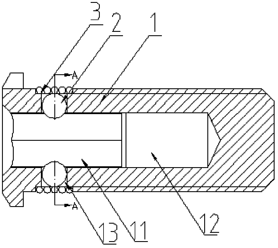
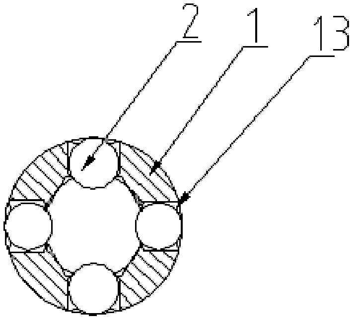
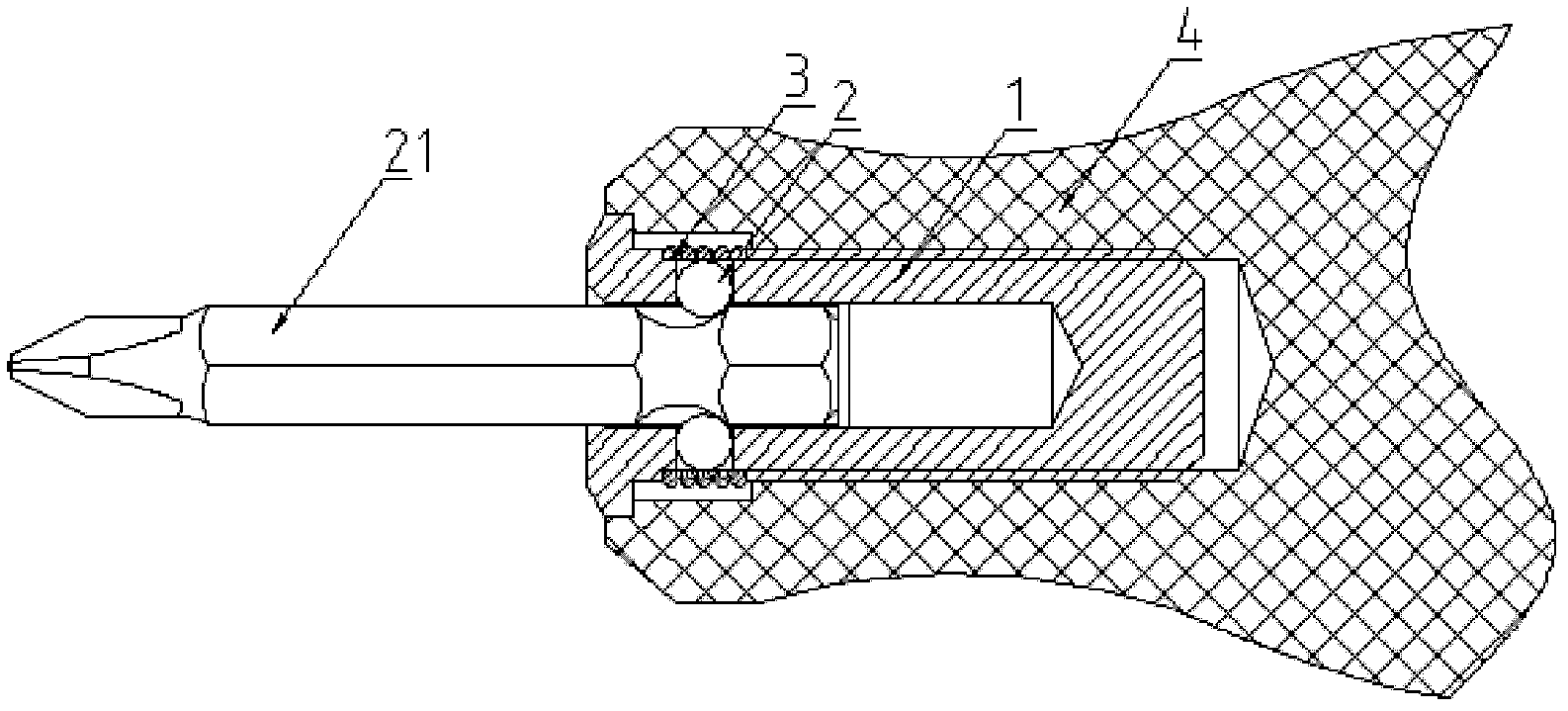
[0043] Embodiment: A multi-purpose joint seat, including a mandrel 1 and a first ball 2, the inner side of the mandrel 1 from one end to the other end is successively provided with an axial installation groove 11 (generally a hexagonal groove for inserting the workpiece 21) Tool’s hexagonal flute fit), the mandrel 1 is provided with at least one radial first hole 13 which connects the mounting groove 11 in the mandrel 1 with the outside of the mandrel 1, and the sphere is placed on the mandrel In the first hole 13 of 1, the part of the ball close to the mounting groove 11 of the mandrel 1 can extend into the mounting groove 11 without falling, and a first elastic member 3 is also provided, and the first elastic member 3 axially stops The inner side of the first elastic member 3 is tightly sleeved on the outer side of the mandrel 1, and the inner side of the first elastic member 3 tightly tops the side of the sphere facing away from the installation groove 11 of the mandrel 1. The structure inside the slot 11 and not falling is: the diameter of the opening of the first hole 13 on the mandrel 1 along the radial inner side of the mandrel 1 is smaller than the diameter of the first sphere 2, of course, a stopper may be provided inside the first hole 13 6; When the joint seat is used, insert the hexagonal workpiece 21 into the mounting groove 11 of the mandrel 1, the first sphere 2 is squeezed by the hexagonal workpiece 21 and moves outward along the first hole 13, and the inner wall of the first elastic member 3 is subjected to the first A sphere 2 is squeezed and deformed. When the hexagonal workpiece 21 is inserted to the bottom, the first sphere 2 tightly squeezes the outer side wall of the hexagonal workpiece 21 under the action of the deformation elastic force of the first elastic member 3, and clamps it. For the hexagonal workpiece 21 with a groove, the first sphere 2 is tightly clamped into the groove of the hexagonal workpiece 21, and the hexagonal workpiece 21 is clamped and positioned in all directions in the radial and axial directions. The elastic deformation realizes the compaction of the first sphere 2, the structure is simple, practical and convenient, and the positioning is stable.
[0044] A rear sleeve 5, a stopper 6 and a second elastic member 7 are also provided. The rear sleeve 5 is axially slidably sleeved on the outer side of the mandrel 1, and the second elastic member 7 is sleeved on the outer side of the mandrel 1. 1 An annular first radial protrusion 14 is provided on the outer side wall of the other end (which can be matched with a circlip by a gasket, and has the same function). The two ends of the second elastic member 7 are respectively pressed against the other end of the back sleeve 5. The end surface of the mandrel 1 and the annular protrusion at the other end of the mandrel 1, the stopper 6 is fixed on the outside of one end of the mandrel 1, the stopper 6 is stopped on the axial end surface of the rear sleeve 5, and the rear sleeve 5 is manually slid backwards , Insert the hexagonal work piece 21, after the work is inserted to the end, release the back sleeve 5, under the elastic force of the second elastic piece 7, the inner side of the back sleeve 5 presses the first elastic piece 3 to clamp the work piece 21, On the contrary, if the back sleeve 5 is slid backwards, and the back sleeve 5 is separated from the first elastic member 3, the workpiece 21 can be pulled out. This prevents the workpiece 21 from deforming the first elastic member 3 due to the huge external force in the axial direction. Pull out, it is better to provide a truncated cone hole with a tapered diameter at the inner end of the back sleeve 5. There is a set gap between the inner side wall of the truncated cone hole and the outer side wall of the first elastic member 3, so that When the sleeve 5 moves to the side of the first elastic member 3 under the elastic force of the second elastic member 7, it can ensure that the first elastic member 3 smoothly enters the back sleeve 5 and prevent interference.
[0045] The inner side of the rear sleeve 5 is a T-shaped hole with one end smaller than the diameter of the other end. The second elastic member 7 is located between the rear sleeve 5 and the mandrel 1, and the second elastic member 7 is tightly pressed against one end of the rear sleeve 5 in the axial direction. The step surface of the hole.
[0046] An outer sleeve 8, a sliding pin 9 and a third elastic member 10 are also provided. The outer sleeve 8 can be slidably sleeved on the outside of the rear sleeve 5 in the axial direction. The mandrel 1 is provided with a circular groove 12 coaxially communicating with the mounting hole. The pin 9 can be slidably inserted into the circular groove 12 of the mandrel 1 in the axial direction. One end of the sliding pin 9 can be elastically partially extended into the installation groove 11, and the outer sleeve 8 can drive the rear sleeve 5 to slide axially. The member 10 is sleeved on the outside of the rear sleeve 5. The axial ends of the third elastic member 10 are respectively tightly pressed against the other end of the outer sleeve 8 and a side surface of the first radial protrusion 14 of the mandrel 1, and one end of the outer sleeve 8 stops At the other end of the stopper 6, insert the grooved hexagonal workpiece 21 into the mounting groove 11 of the mandrel 1 under the action of external force, push the first ball 2 to move outward, and push the sliding pin 9 toward the mandrel 1 Move in the groove 12, when the hexagonal workpiece 21 is inserted to the end, the first sphere 2 at the front end falls into the groove of the hexagonal workpiece 21, at this time the hexagonal workpiece 21 is clamped and positioned; the jacket 8 is under the action of external force Moving backward, the outer sleeve 8 drives the rear sleeve 5 to move backward. When the rear sleeve 5 slides to a certain position, the inner hole of the rear sleeve 5 is separated from the first elastic member 3, and the sliding pin 9 in the mandrel 1 is pushed by the elastic force The hexagonal workpiece 21 is pushed out to the outside of the mandrel 1. Since the first elastic member 3 presses the first ball to keep it clamped with the outer side of the hexagonal workpiece 21, the hexagonal workpiece 21 is pushed out but will not fall and can be easily pulled out at this time Screwdriver head out.
[0047] The outer sleeve 8 can drive the rear sleeve 5 to slide axially in a structure: an annular second radial protrusion 18 is provided on the outer side wall of the rear sleeve 5, and an annular boss that expands radially inward is provided on the inner side of the outer sleeve 8. The other end of the annular boss stops at one side of the second radial protrusion 18 on the outer side wall of the rear sleeve 5.
[0048] The outer circumferential surface of the middle section of the sliding pin 9 is a T-shaped cylinder with an outer diameter of one end smaller than the outer diameter of the other end. The outer circumferential surfaces of the two ends of the sliding pin 9 are respectively radially outwardly-expanding annular stoppers, and the inner side of the rear sleeve 5 The inner diameter of the other end is in a retracted structure, an annular gap 19 is formed between the inner side wall of one end of the inner sleeve and the outer side wall of the mandrel 1, and the inner side of the back sleeve 5 has a retracted structure at the other end to form the end wall of the other end of the ring gap 19 , The mandrel 1 is also provided with at least one radial second hole 20, the second hole 20 is closer to the other end of the mandrel 1 relative to the first hole 13, the second hole 20 is movably provided with a second ball 15 The inner side of the second ball 15 along the axial direction of the second hole 20 is tightly against the outer side wall of the middle section of the sliding pin 9, and the second ball 15 can extend into the inner sleeve and the core shaft 1 along the outer side of the second hole 20 in the axial direction. In the annular gap 19 between and stop at the two ends of the annular gap 19 along the axial direction of the mandrel 1, insert the grooved hexagonal workpiece 21 into the hexagonal hole of the mandrel 1 under the action of external force, Push the first ball 2 to move outwards and push the sliding pin 9 to move backwards. When the hexagonal workpiece 21 is inserted to the end, the first ball 2 falls into the groove of the hexagonal workpiece 21, and the second ball 15 is separated from the rear sleeve 5. Falling into a slot with a small outer diameter of the sliding pin 9, the outer sleeve 8 and the rear sleeve 5 are pushed forward under the action of elastic force to press the first elastic member 3, and the first elastic member 3 presses the first ball 2 and then Clamp the hexagonal workpiece 21; under the action of external force, the outer sleeve 8 is moved backward, and the outer sleeve 8 drives the rear sleeve 5 to move backward. When the rear sleeve 5 slides to a certain position, the sliding pin 9 in the mandrel 1 acts on elastic force Push the hexagonal workpiece 21 forward, the second sphere 15 on the sliding pin 9 is pushed out into the groove with the larger outer diameter of the sliding pin 9, and the outer surface of the second sphere 15 and the inner diameter of the back sleeve 5 are retracted. Stop and fix the inner sleeve so that the inner sleeve is separated from the first elastic part 3, and at the same time, the sliding pin 9 pushes the hexagonal workpiece 21 forward. Because the first elastic part 3 presses the first sphere 2, the first sphere 2 is opposed to the hexagonal workpiece 21 Keep the clamped state so that the first sphere 2 only clamps the hexagonal workpiece 21 in the radial direction without interference in the axial direction, so that the hexagonal workpiece 21 is pushed out but does not fall. At this time, the screwdriver head can be easily pulled out. This structure realizes sliding The pin 9 and the back sleeve 5 cooperate with each other to realize the automatic clamping of the inserted workpiece 21 and the automatic withdrawal of the outer sleeve 8 by pulling the outer sleeve 8 once, which is more convenient to use.
[0049] The sliding pin 9 has a structure in which one end of the sliding pin 9 can be elastically partially extended into the installation groove 11: the other end of the sliding pin 9 is provided with a blind hole, and the blind hole is provided with a fourth elastic member 16 and two fourth elastic members 16 The ends respectively elastically press against the inner wall end wall of the blind hole and the inner end wall of the circular groove 12 of the mandrel 1.
[0050] A handle 4 is also provided. The handle 4 is fixedly sleeved on the outer side of the other end of the mandrel 1. The other end of the mandrel 1 can also form a hexagonal prism structure. The hexagonal prism is provided with a ring-shaped inner groove, which can make it compatible with other The street seat is fixedly connected, which is convenient for applying force to the hexagonal workpiece 21, and multiple joint seats can be arranged on one handle 4, which is more convenient to use.
[0051] A tail sleeve 17 is also provided, and the tail sleeve 17 is axially stopped and can be rotatably positioned at the other end of the mandrel 1 in the circumferential direction.
[0052] The first strip holes are arranged in a uniform array along the axial and circumferential directions of the mandrel 1.
[0053] In this example, the first and second spheres are steel balls, and the first, second, third, and fourth elastic members are all springs.

PUM

no PUM

Description & Claims & Application Information

We can also present the details of the Description, Claims and Application information to help users get a comprehensive understanding of the technical details of the patent, such as background art, summary of invention, brief description of drawings, description of embodiments, and other original content. On the other hand, users can also determine the specific scope of protection of the technology through the list of claims; as well as understand the changes in the life cycle of the technology with the presentation of the patent timeline. Login to view more.

Similar technology patents

Shrinkage fit and positioning tool for stator core and casing

PendingCN108723699Aprecise positioningImprove concentricity
Owner:WENLING JIUZHOU ELECTROMECHANICAL

Aortic valve device conveyed by catheter

InactiveCN105496607Areduce paravalvular leakprecise positioning
Owner:BEIJING MED ZENITH MEDICAL SCI CORP LTD

Welding jig for welding cylinder

InactiveCN1966200Aprecise positioningEasy and reliable clamping
Owner:HUAZHONG UNIV OF SCI & TECH

Positioning fixture tool

ActiveCN103639799AFlexible usageprecise positioning
Owner:ZHEJIANG DEHONG AUTOMOTIVE ELECTRONICS & ELECTRICAL

Classification and recommendation of technical efficacy words

  • easy to use
  • precise positioning

Laser assisted total joint arthroplasty

InactiveUS20090234360A1easy to use
Owner:ALEXANDER VLADIMIR

Enclosure for a portable hemodialysis system

ActiveUS20090114582A1easy to use
Owner:DEKA PROD LLP

Method of mobile phone navigation in library and system

InactiveCN102384745AThe realization principle is simpleprecise positioning
Owner:NANJING UNIV OF INFORMATION SCI & TECH

Unmanned vehicle, and unmanned vehicle positioning method, device and system

ActiveCN106023210Aprecise positioningAvoid large positioning errors
Owner:BAIDU ONLINE NETWORK TECH (BEIJIBG) CO LTD

Electrical connector with releasable pick-up device

InactiveUS6439901B1precise positioning
Owner:HON HAI PRECISION IND CO LTD

Universal modular wafer transport system

InactiveUS7293950B2precise positioning
Owner:BOOKS AUTOMATION US LLC
Why Eureka
Try Eureka