Airbag plastic mould

A technology for plastic molds and airbags, applied in the field of plastic molds for airbags, can solve the problems of inconvenient automatic reclaiming mechanism reclaiming operation, easy generation of flash, and easy falling of products.

Active Publication Date: 2015-04-22
宁海县现代模具有限公司
View PDF6 Cites 0 Cited by
  • Summary
  • Abstract
  • Description
  • Claims
  • Application Information

AI Technical Summary

Problems solved by technology

Due to the large body of the inclined ejector, it is easy to produce a gap between the wall of the inclined ejector socket on the movable mold core during the retraction process. This gap makes the inclined ejector, the movable mold core and the product common Flashing is easy to appear at the junction, which affects the use of the product
In addition, due to the limitation of the structure, the inclined roof can only be pushed on one side of the product. When the product is pushed out of the mold core by the inclined roof, the product is easy to fall from the inclined roof due to the inertia force, which is not convenient for automatic removal. Material mechanism for reclaiming operation
To sum up, the plastic molds for airbags in the prior art have the disadvantages that the joint between the inclined roof and the product and the moving mold core is prone to flash, and the product is easy to fall when it is ejected.

Method used


Image

  • Airbag plastic mould
  • Airbag plastic mould
  • Airbag plastic mould

Examples


Embodiment Construction

[0017] The present invention will be described in further detail below in conjunction with the accompanying drawings.

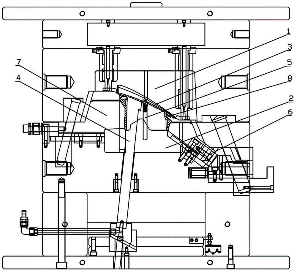
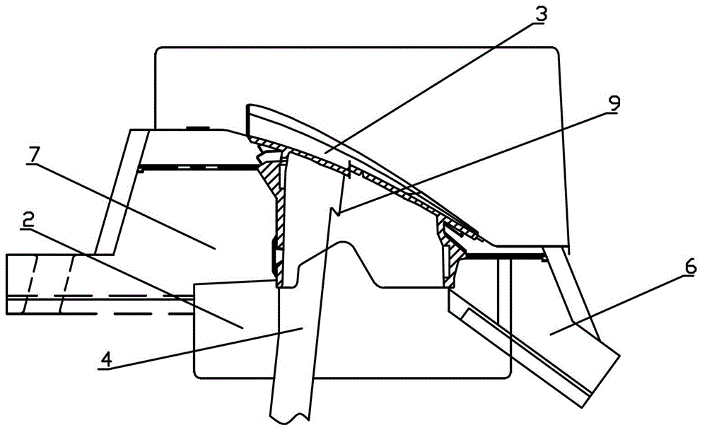
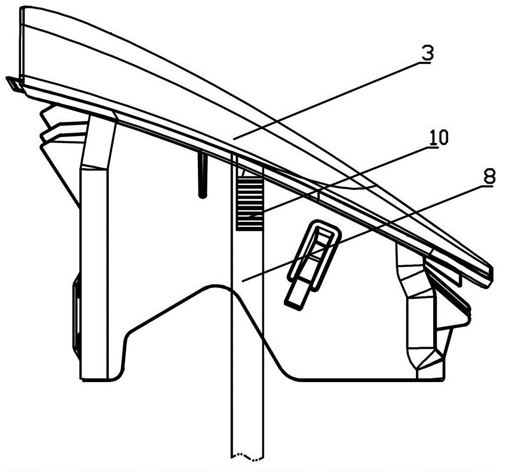
[0018] combined with figure 1 to attach Figure 7 , an airbag plastic mold, which includes a fixed mold core 1, a movable mold core 2 and a product cavity 3 between the two; the product cavity 3 is connected with an inclined top 4, a right slider 6 and a left slider Block 7; the inclined top 4 slides and fits with the movable mold core 2 at the same time, one side of the upper end of the inclined top 4 is directly connected with the product cavity 3, and the other side is in contact with the movable mold core 2; An undercut 9 is provided on the side where the upper end is attached to the movable mold core 2, and a button position interlocking with the undercut 9 is provided on the movable mold core 2; the product cavity 3 is also connected with an anti-dropping needle 5, Serrations 10 are provided at the contact between the side of the anti-fall needle 5 an...


PUM


Abstract

The invention provides an airbag plastic mould in which junctures of a lifter and a product as well as a moving core are less prone to generation of flash and the product is less prone to falling when ejected out. The airbag plastic mould comprises a fixed core (1), the moving core (2) and a product cavity (3) positioned between the fixed core and the moving core, the lifter (4), a right slider (6) and a left slider (7) are connected onto the product cavity (3) respectively, the lifter (4) is in sliding sleeved fit with the moving core (2), and one side of the upper end of the lifter (4) is directly connected with the product cavity (3) while the other side of the same is attached to the moving core (2). The airbag plastic mould is characterized in that a reverse button (9) is arranged on one side, attached to the moving core (2), of the lifter (4), a button buttoned with the reverse button (9) is arranged on the moving core (2), an anti-falling needle (5) is further connected onto the product cavity (3), and saw teeth (10) are arranged at a contacting position of the side face of the anti-falling needle (5) and the product cavity (3).

Description

technical field [0001] The invention relates to a plastic mold for an airbag. Background technique [0002] In the prior art, the airbag plastic mold comprises essential components such as a fixed mold core, a moving mold core, an inclined roof and a slide block. However, due to the complex structure of the airbag product, the reliability and design requirements for the inclined roof and the slider are relatively high. The slanted roof structure used for airbags in the prior art is the most commonly used structure by technicians in the industry, and is mainly made of a slanted rod with a smooth appearance. When this structure is used in the airbag plastic mold, the inclined roof is generally designed to be relatively large. One side of the inclined roof is the product, and the other side is the moving mold core. After the product is formed, the inclined top pushes the product out of the movable mold core upwards. After the worker or the automatic feeding mechanism takes th...

Claims


Application Information

Patent Timeline
Patent Type & Authority Patents(China)
IPC IPC(8): B29C45/26B29C45/40
Inventor 葛文枝
Owner 宁海县现代模具有限公司
Why Eureka
Try Eureka