Automobile seat air-conditioning system

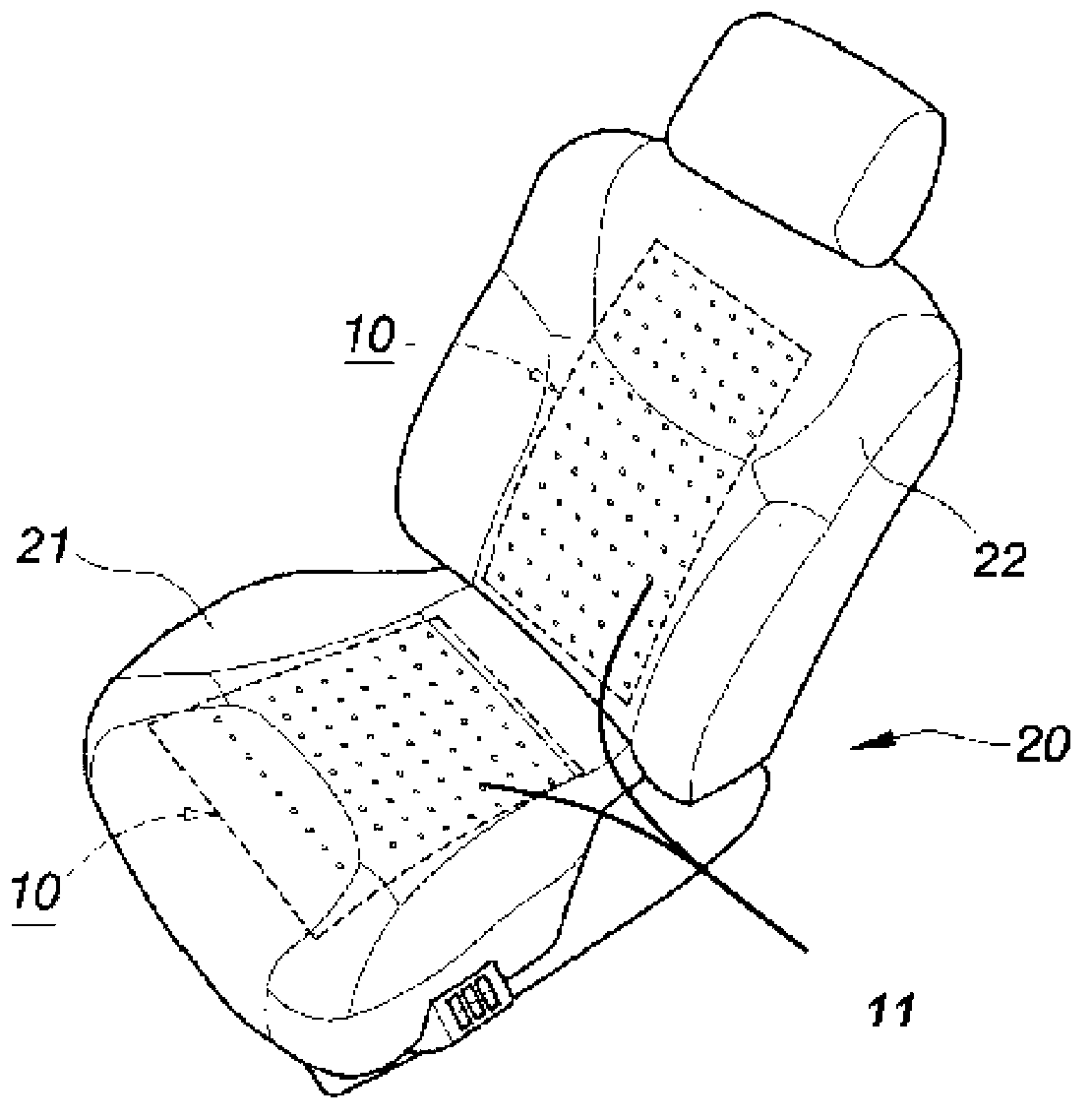
A technology for air conditioning systems and car seats, which is applied to seat heating/ventilation devices, etc., can solve problems such as the inability to provide gas transmission of the back pad 22

Inactive Publication Date: 2013-07-17
张家杰
View PDF10 Cites 5 Cited by
  • Summary
  • Abstract
  • Description
  • Claims
  • Application Information

AI Technical Summary

Problems solved by technology

[0004] The traditional air-conditioning system for car seats uses straight conduits to direct...

Method used


Image

  • Automobile seat air-conditioning system
  • Automobile seat air-conditioning system
  • Automobile seat air-conditioning system

Examples


Embodiment 1

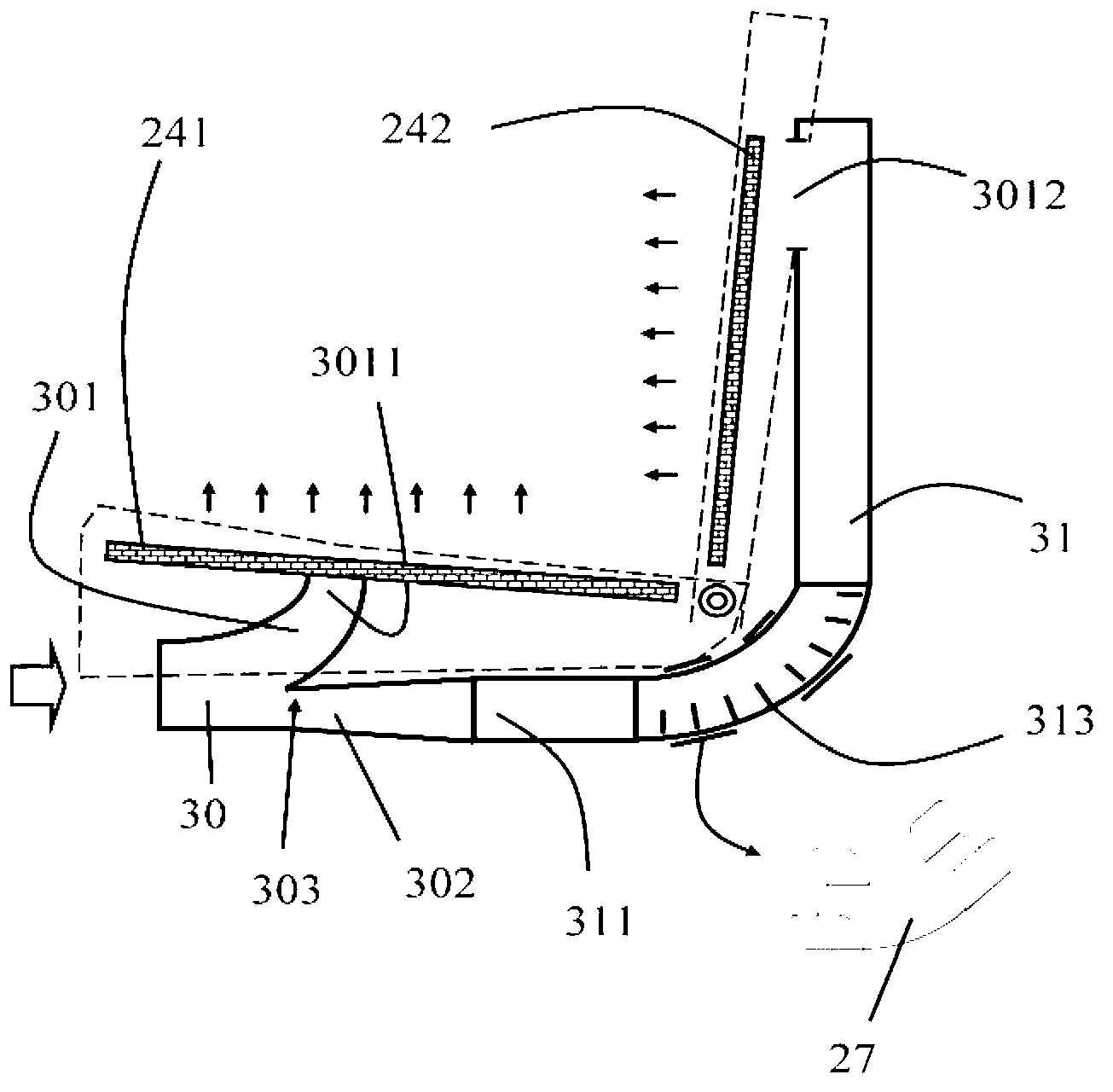
[0049] Such as image 3 As shown, the car seat air-conditioning system provided by Embodiment 1 of the present invention includes: a car seat cushion (shown as a dotted line) and a shunt pipe 30. And the second distribution channel 302, the first distribution channel 301 extends from the left air intake opening in an arc to the upper right, and the inner wall of the channel bends upwards in an arc shape, forming the first air outlet opening 3011 upward; the second distribution channel extends from the left air intake opening Extending to the right, forming a right connection opening 311 . Wherein, the bottom of the tube wall of the first distribution channel 301 intersects with the top of the tube wall of the second distribution channel 302 at a tangent line, and a tip 303 is formed in the distribution tube toward the left air inlet opening. The tip 303 can reduce the airflow resistance of the intake air, so that the air-conditioning gas can flow smoothly in the distribution ...

Embodiment 2

[0053] Such as Figure 4 As shown, in the car seat air-conditioning system provided by the second embodiment of the present invention, the first air outlet fan 251 is arranged in the second air outlet opening 3012 to blow the air to the back of the seat. An air intake fan 252 can be arranged at the air intake opening to blow air into the distribution pipe 30 . If it is necessary to provide hot air for the seat cushion 21, the heating unit H01 can be placed above the wind direction diffusion net 241; All the other structures are the same as in Embodiment 1.

[0054] Such as Figure 9 As shown, the heating units H01 and H02 of this embodiment can be heating wires 321 placed on the flexible substrate 32; and a plurality of ventilation openings 322 are opened near the heating wires 321, and the ventilation openings 322 provide air-conditioning air to pass through. use. The heating wire 321 can be metal wire or carbon fiber wire.

[0055] Such as Figure 10 As shown, the heat...

Embodiment 3

[0057] Such as Figure 5 As shown, in the car seat air-conditioning system provided by Embodiment 3 of the present invention, the heating unit H03 can be arranged at the air inlet of the shunt pipe 30, and the fan 252 is arranged on the left side of the heating unit H03. When it is windy, hot air can be provided to the seat cushion 21 and the back cushion 22. All the other structures are with embodiment two.


PUM


Abstract

The invention discloses an automobile seat air-conditioning system which includes an automobile seat cushion and a flow divider pipe, wherein the flow divider pipe is arranged below the automobile seat cushion. Further, the flow divider pipe includes a left air inlet opening, a first flow dividing channel and a second flow dividing channel, wherein the first flow dividing channel extends from the arc of the left air inlet opening to upward right, a channel inner wall is winding upward in an arc shape, and thus an upward first air outlet opening is formed; the second flow dividing channel extends from the left air inlet opening to the right and a right connection opening is formed; a lower part of the pipe wall of the first flow dividing channel is connected in a tangent manner with an upper part of the pipe wall of the second flow dividing channel, and a tip facing the left air inlet opening is formed in the flow divider pipe. The automobile seat air-conditioning system having the arc-shaped flow divider pipe provides a fan for transverse air intake for the flow divider pipe, and guides the air-conditioning air intake to smoothly upward right to the seat cushion by using the arc-shaped flow divider pipe. The automobile seat air-conditioning system can at the same time guide the air-conditioning air flow to the back of the seat to adjustment temperature at the back for a driver.

Description

technical field [0001] The invention relates to an air-conditioning system for a car seat, in particular to an air-conditioning system for a car seat with an arc-shaped shunt pipe to deliver the air-conditioning airflow to the seat of the car with the least resistance. Another design of this system is to transmit the air-conditioning air to the seat and the back of the seat at the same time. Background technique [0002] Such as figure 1 Shown is a common traditional car seat. The figure shows that a traditional car seat 20 includes a seat cushion 21 and a back cushion 22. The outer seat cover has many small ventilation holes 11 in the ventilation area 10 of the seat cushion 21 and the back cushion 22. , the airflow that provides the seat cushion 21 and the back cushion 22 is common to the outflow. [0003] Such as figure 2 Shown is a common traditional car seat air-conditioning system. The figure shows a traditional car seat air-conditioning system, which includes a low...

Claims


Application Information

Patent Timeline
IPC IPC(8): B60N2/56
Inventor 张家杰
Owner 张家杰
Why Eureka
Try Eureka