Eureka AIR delivers breakthrough ideas for toughest innovation challenges, trusted by R&D personnel around the world.

Adjustment mechanism for ground irradiation lamp on rear view mirror outside automobile

A technology of exterior rearview mirror and adjustment mechanism, which is applied to vehicle parts, optical observation devices, optical signals, etc., can solve the problems of small irradiation area, unable to illuminate the vehicle, unable to adjust the lighting of the floor, etc., and achieves good stability, The effect of ensuring safety

Inactive Publication Date: 2013-07-17
力帆科技(集团)股份有限公司
View PDF6 Cites 2 Cited by
  • Summary
  • Abstract
  • Description
  • Claims
  • Application Information

AI Technical Summary

Problems solved by technology

Existing floor lamps are fixedly installed at the bottom of the rearview mirror housing, and cannot be adjusted in comparison with the irradiation area of ​​the floor lamp. The irradiation area is small and only limited to just below the exterior rearview mirror. The lighting is provided for getting on and off the vehicle, but it cannot illuminate the side and rear of the vehicle. The driver cannot clearly observe the road conditions behind the vehicle when reversing at night, so it has no effect on the safety of reversing at night.
In addition, the floor lamp is directly fixed on the bottom of the rearview mirror housing through bolts, and the floor lamp protrudes downward from the bottom of the rearview mirror, which will not only affect the appearance of the rearview mirror, but also easily damage the floor lamp

Method used


Image

  • Adjustment mechanism for ground irradiation lamp on rear view mirror outside automobile
  • Adjustment mechanism for ground irradiation lamp on rear view mirror outside automobile
  • Adjustment mechanism for ground irradiation lamp on rear view mirror outside automobile

Examples


Embodiment Construction

[0017] Below in conjunction with accompanying drawing and embodiment the present invention will be further described:

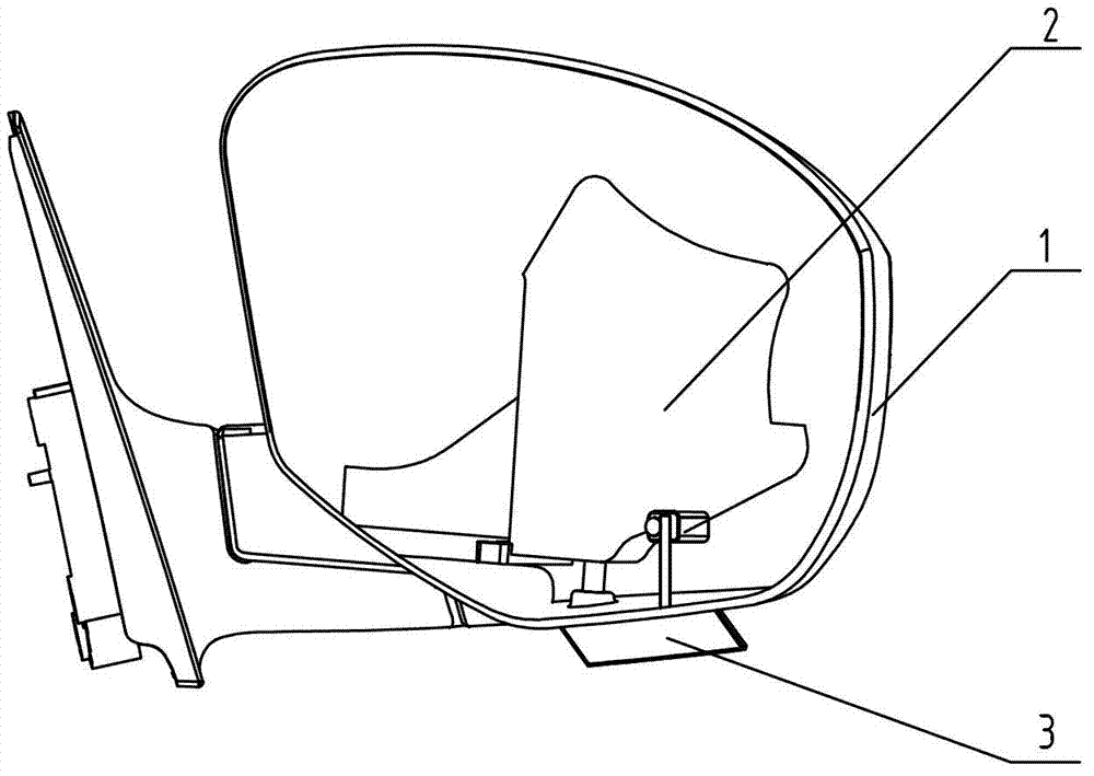
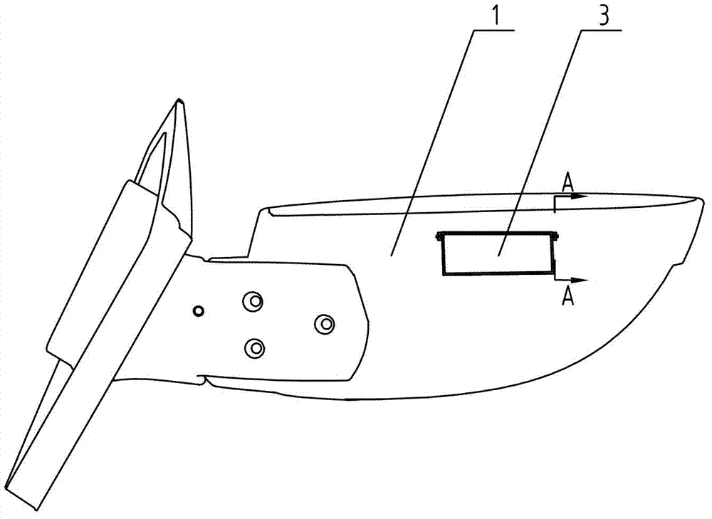
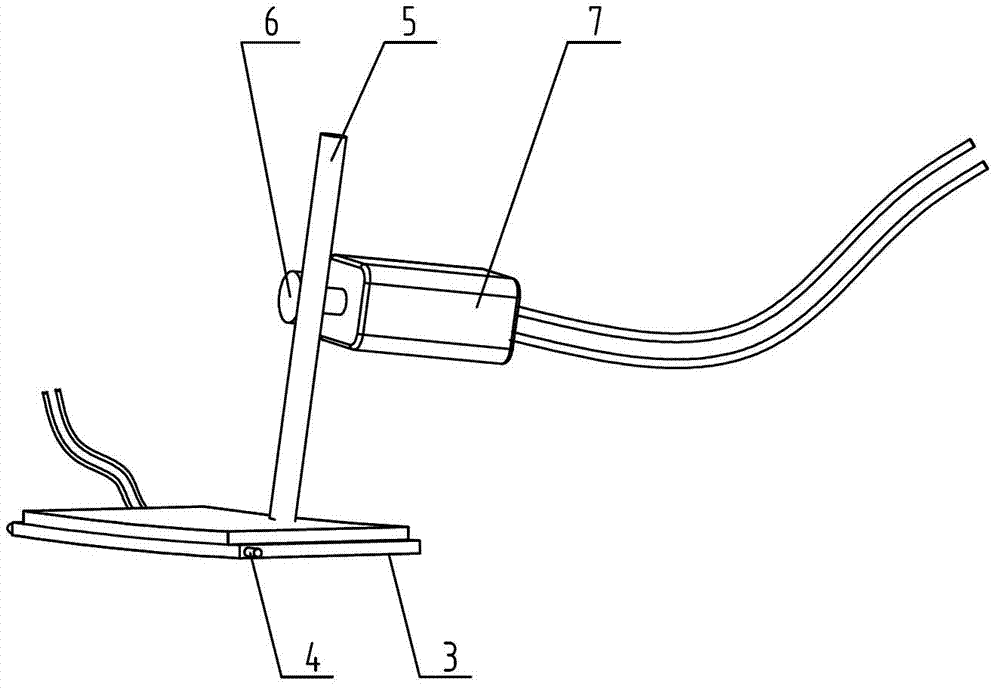
[0018] Such as figure 1 , figure 2 , image 3 , Figure 4 and Figure 5 Shown, the present invention is made of rearview mirror housing 1, rearview mirror bracket 2, floor lamp 3, rotating shaft 4, worm screw 5, worm wheel 6, motor 7, " U " shape steel band 8 and screw 9 etc. Wherein, the rearview mirror bracket 2 is installed in the rearview mirror housing 1, and a window whose shape and size are compatible with the floor lamp 3 is opened at the bottom of the rearview mirror housing 1, and the floor lamp 3 in this window. In this embodiment, the floor lamp 3 and the window are preferably rectangular. On the left and right sides of the front end of the floor lamp 3, rotating shafts 4 are symmetrically fixed, and the axes of the two rotating shafts 4 are on a straight line, and each rotating shaft 4 is snapped into a corresponding groove provided at the...


PUM


Abstract

The invention discloses an adjustment mechanism for a ground irradiation lamp on a rear view mirror outside an automobile. The adjustment mechanism comprises a rear view mirror shell, a rear view mirror rack and the ground irradiation lamp, wherein the rear view mirror rack is arranged in the rear view mirror shell; a window of which the shape and the size are matched with those of the ground irradiation lamp is formed in the bottom of the rear view mirror shell; the ground irradiation lamp is positioned in the window; the left side and the right side of the ground irradiation lamp are hinged with the rear view mirror shell through rotating shafts; a worm is arranged above the ground irradiation lamp and is positioned behind the rotating shafts; the bottom of the worm is fixed on the upper surface of the ground irradiation lamp; the worm is meshed with a worm wheel; the worm wheel is sleeved on an output shaft of a motor; and the motor is arranged on the rear view mirror rack. The adjustment mechanism can adjust an irradiation region of the ground irradiation lamp, so that the ground irradiation lamp can irradiate the lateral rear side of the automobile; and the safety of backing off at night is guaranteed, and the ground irradiation lamp is difficult to damage.

Description

technical field [0001] The invention belongs to the field of automobile lighting, and in particular relates to an adjustment mechanism for a floor lamp of an automobile exterior rearview mirror. Background technique [0002] With the continuous improvement of people's living standards in today's society, more and more families own cars. When people go out to do errands and travel to their destination, they need to park their vehicles in a relatively safe place. During the day, due to the better light, the driver can clearly observe the surrounding position of the vehicle, thereby parking and starting the vehicle safely, and the occupants can also get on and off the vehicle safely. But at night, because many places do not install lighting systems, the driver's vision is dim, and the situation around the vehicle is not clear, so it is quite difficult to park and start the car, especially when the roads around the car are complicated and the sundries are relatively large. In ...

Claims


Application Information

Patent Timeline
Patent Type & Authority Applications(China)
IPC IPC(8): B60R1/12B60Q1/02
CPCB60Q1/2665B60Q1/22
Inventor 唐飞
Owner 力帆科技(集团)股份有限公司
Why Eureka
Eureka Blog
Learn More