
led motorcycle tail light

A technology for motorcycles and taillights, applied to lampshades, motor vehicles, road vehicles, etc., can solve the problems of limited flexibility in styling design, increased taillight costs, poor contact, etc., achieve good appearance and visual effects, enhance internal reflection performance, Uniform and soft glow effect

Inactive Publication Date: 2016-01-20
NINGBO LONGJIA MOTORCYCLE
View PDF7 Cites 0 Cited by
  • Summary
  • Abstract
  • Description
  • Claims
  • Application Information

AI Technical Summary

Problems solved by technology

Because the light bulb adopts an ordinary incandescent lamp, this kind of light source has large volume, high power, high heat generation, relatively short service life, and poor brightness. At the same time, the installation structure of the light bulb and the base (reflector) is not very reliable. Due to vibration, it is easy to cause the bulb to loosen, poor contact and other faults, which will cause the taillight to fail and endanger the personal safety of motorcycle drivers and passengers
Moreover, the common light source limits the flexibility of the shape design of the whole lamp, and the shape of the reflector is relatively simple.
For this reason, some motorcycle manufacturers use LED lamps to replace incandescent bulbs, but the price of LED lamps is relatively high, which will not only increase the cost of tail lights, but also must change the structure of lamp holders and masks to adapt to the installation of LED lamps. There are major changes in the structure, and the transformation cost is high

Method used


Image

  • led motorcycle tail light
  • led motorcycle tail light
  • led motorcycle tail light

Examples


Embodiment Construction

[0020] The present invention will be described in further detail below in conjunction with the accompanying drawings and specific embodiments.

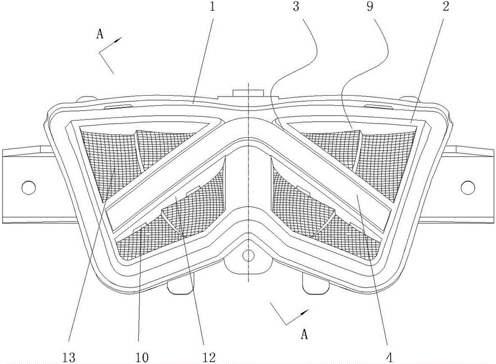
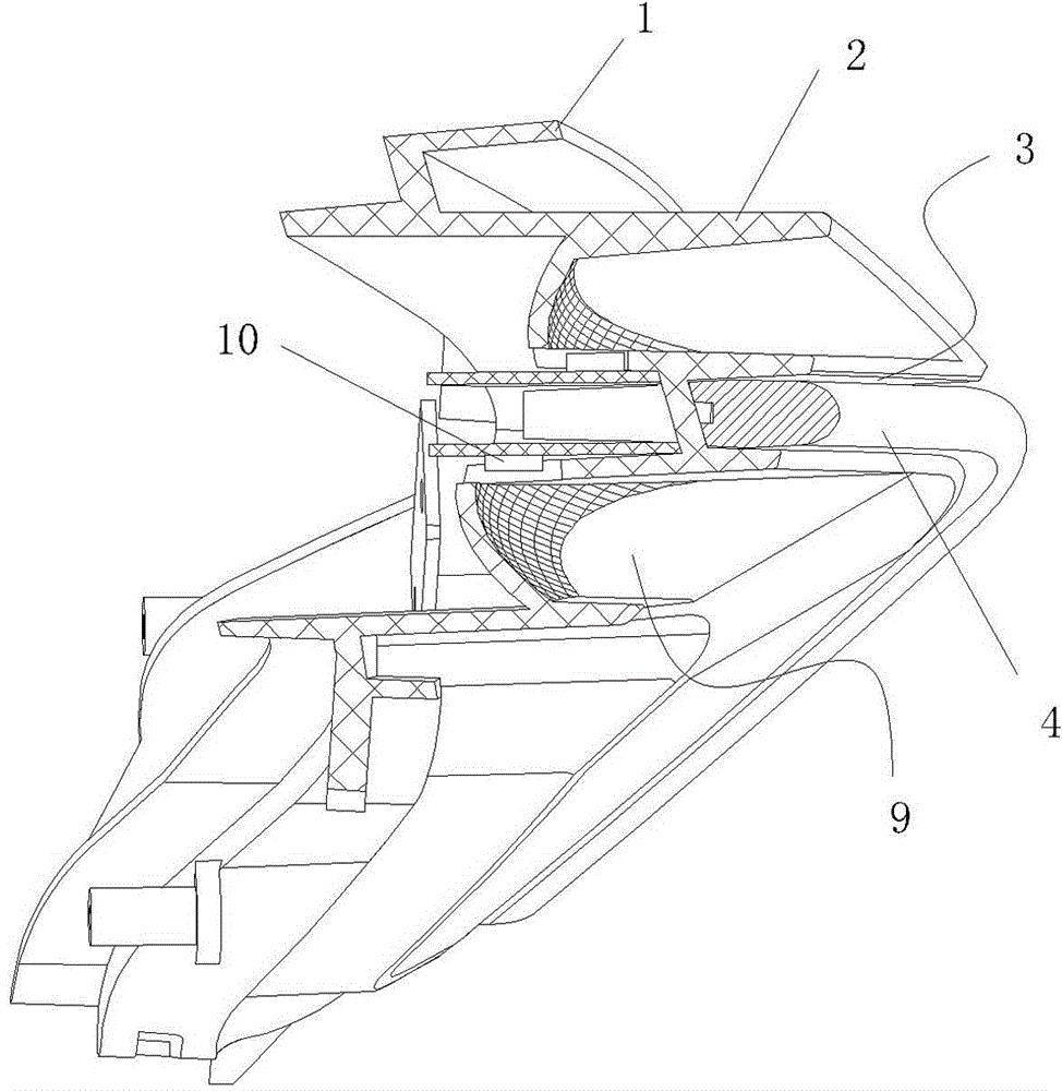
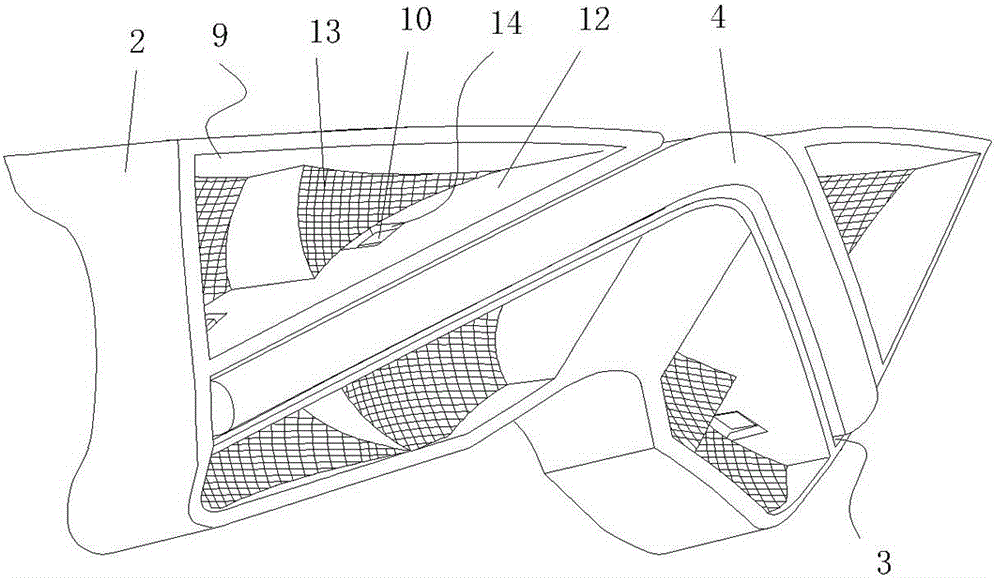
[0021] refer to Figure 1~Figure 6 , an LED motorcycle tail light, comprising a base 1 with an inner cavity, an LED lighting assembly disposed in the inner cavity, and a mask covering the base 1, the LED lighting assembly includes a base mounted on the base 1 The lamp holder 2 in the inner cavity of the lamp holder 2 is provided with a fixing groove 3 in the middle of the lamp holder 2. The shape of the fixing groove 3 is a V-shaped structure with the opening facing forward. Matching V-shaped light guide strip 4, the front of the light guide strip 4 is the light emitting surface, the back of the light guide strip 4 is concavely provided with a groove 5, and the groove 5 is provided with a reflective surface with serrated protrusions 6. The middle part of the two ends of the light guide strip 4 is concavely provided with a mounting gr...


PUM


Abstract

The invention relates to an LED (Light Emitting Diode) taillight for a motorcycle. The taillight comprises a base, an LED light emitting assembly and a mask, wherein the LED light emitting assembly comprises a lamp holder installed in a cavity of the base; a fixed groove is arranged in the middle of the lamp holder in a concave manner; the fixed groove is in a V-shaped structure with a forward opening; the fixed groove is internally provided with a V-shaped light guide bar; the front face of the light guide bar is a beam emitting face; a groove is arranged in the back of the light guide bar in a concave manner; the groove is internally provided with a reflective face which is convex in zigzag shape; an installation groove I is arranged in the middle of each end of the light guide bar in a concave manner; the installation groove I is internally provided with an LED retroposition bead; reflective bowls are arranged on the front and rear sides at both ends of the lamp holder located at both ends of the fixed groove; and each reflective bowl is internally provided with an LED brake bead. The taillight provided by the invention has the beneficial effects that LED is used as a light source, so that the taillight of the motorcycle has the advantages of energy saving, environmental friendliness, long service life, small heating amount, high brightness, stable performance and the like; and the light guide bar is in the V-shaped structure which is matched with tail lines of the whole motorcycle, so that the appearance effect is good.

Description

technical field [0001] The invention relates to a motorcycle component, in particular to an LED motorcycle tail light. Background technique [0002] Motorcycle tail lights (brake lights and rear position lights) are one of the important safety parts of motorcycles and one of the important decorative parts of motorcycles. The current motorcycle tail light is generally composed of a base, a reflector, a bulb and a mask. The reflector is installed in the cavity of the base, the bulb is installed in the center of the reflector, and the base is covered with a mask. The bulb is divided into rear bulbs. And the brake bulb, the rear bulb is always on, the brake bulb is on when braking, part of the light from the bulb directly shines on the mask and emits outward through the mask, and the other shines on the reflector through reflection The mirror reflects and emits outward through the visor to warn pedestrians and vehicles behind. Because the light bulb adopts an ordinary incandes...

Claims


Application Information

Patent Timeline
Patent Type & Authority Patents(China)
IPC IPC(8): B62J6/04F21S8/10F21V3/02F21V8/00F21W101/027F21W101/14F21Y101/02F21W107/17F21Y115/10
Inventor 徐勇
Owner NINGBO LONGJIA MOTORCYCLE
Learn More