
Rotary hydraulic system and construction machinery

A hydraulic system and construction machinery technology, applied in the field of hydraulic pressure, can solve problems affecting handling performance, brake lockup, strong impact, etc., to achieve the effect of preventing the car from rolling, reducing the impact feeling, and improving the handling performance

Active Publication Date: 2015-04-22
SANY AUTOMOBILE HOISTING MACHINERY
View PDF6 Cites 0 Cited by
  • Summary
  • Abstract
  • Description
  • Claims
  • Application Information

AI Technical Summary

Problems solved by technology

[0003] In view of this, the present invention aims to propose a slewing hydraulic system and engineering machinery to solve the problem of strong impact caused by brake lock, which affects the handling performance and operating comfort

Method used


Image

  • Rotary hydraulic system and construction machinery

Examples


Embodiment Construction

[0039] It should be noted that, in the case of no conflict, the embodiments of the present invention and the features in the embodiments can be combined with each other. The present invention will be described in detail below with reference to the accompanying drawings and examples.

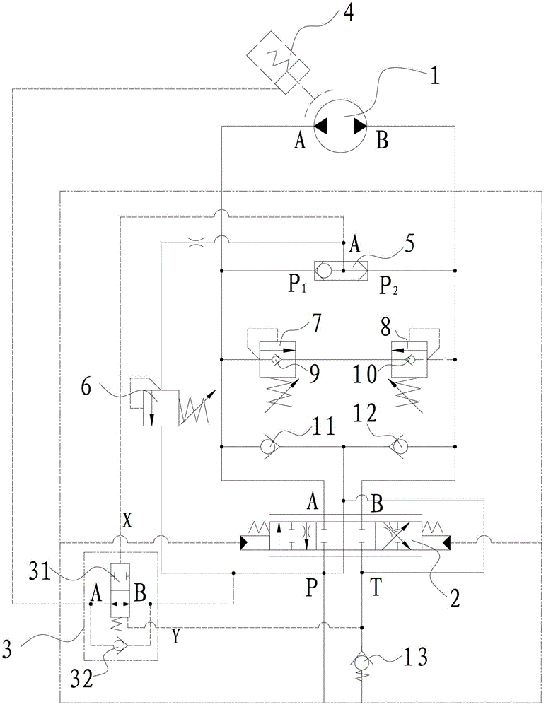
[0040] figure 1 It is the hydraulic schematic diagram of the rotary hydraulic system described in the embodiment of the present invention. As shown in the figure, the rotary hydraulic system described in this embodiment includes a rotary motor 1, a brake cylinder 4, a main valve 2, a shuttle valve 5 and a brake Dynamic anti-lock valve 3. The main valve 2 is a three-position six-way hydraulic pilot proportional valve. The brake anti-lock valve 3 includes a first check valve 32 and a hydraulic control reversing valve 31; 1 The port is connected with the A port of the rotary motor 1, and the B port of the main valve 2 is connected with the P port of the shuttle valve 5 at the same time. 2 It comm...


PUM


Abstract

The invention provides a rotary hydraulic system and construction machinery. The rotary hydraulic system comprises a rotary motor, a brake oil cylinder, a main valve, a shuttle valve and a brake anti-lock valve. The brake anti-lock valve includes a first check valve and a hydraulic-control selector valve. An oil return port T of the main valve is communicated with a hydraulic control end Y of the hydraulic-control selector valve. An oil inlet port P is communicated with an oil return port of the first check valve and a port B of the hydraulic-control selector valve synchronously. A hydraulic control end X of the hydraulic-control selector valve is communicated with a port A of the shuttle valve. The port A of the shuttle valve and an oil outlet port of the first check valve are communicated with the brake oil cylinder synchronously. The main valve is communicated with the oil inlet port P and the oil return port T while a valve core is positioned at the center. When a rotary mechanism is rapidly stopped, the hydraulic-control selector valve is closed, the oil inlet port P of the main valve is communicated with the brake oil cylinder through the first check valve to prevent a brake from being closed, and accordingly, only if the rotary mechanism shakes, the brake is not locked, sense of impact is greatly reduced, and operational performance and operational comfort of rotary actions are further improved.

Description

technical field [0001] The invention relates to the field of hydraulic technology, in particular to a rotary hydraulic system and engineering machinery. Background technique [0002] Generally speaking, the rotary brake valves of the existing construction machinery rotary mechanisms are generally one-way throttle valves, so the delayed closing time of the brake depends on the fixed damping of the one-way throttle valve. Under working conditions, no matter how the operation turns, the delay closing time of the brake is a fixed value. However, the moment of inertia of the slewing mechanism of construction machinery is relatively large, and it is easy to cause slewing impact when it stops. Therefore, when the slewing stops quickly, if the slewing mechanism on the vehicle has not stopped shaking, the brake is locked at this time, which will lead to a stronger shock feeling and serious It affects the handling performance and operating comfort of the slewing action. Contents of...

Claims


Application Information

Patent Timeline
Patent Type & Authority Patents(China)
IPC IPC(8): F15B11/02
Inventor 易迪升侯敏刘正雷
Owner SANY AUTOMOBILE HOISTING MACHINERY
Learn More