Bidirectional balanced flow distributor

A flow distributor and equalization technology, which is applied in the direction of fluid circulation arrangement, refrigeration components, refrigerators, etc., can solve the problems of unbalanced flow distribution of each branch, influence on heating performance, etc., and achieve the solution of uneven flow distribution and simple structure Effect

Active Publication Date: 2013-07-17
GUANGZHOU WEIJIN AIR CONDITIONER SCI & TECH
View PDF8 Cites 12 Cited by
  • Summary
  • Abstract
  • Description
  • Claims
  • Application Information

AI Technical Summary

Problems solved by technology

But in heating and cooling air conditioners, when the system is in heating operation, the flow direction of the refrigerant is opposite to the flow direction during cooling. At this time, the flow distributor is equivalent to a confluence. The pipeline resistance characteristics of the branches change, which makes the flow distribution of each branch unbalanced, so the heating performance is affected

Method used


Image

  • Bidirectional balanced flow distributor
  • Bidirectional balanced flow distributor

Examples


Embodiment 1

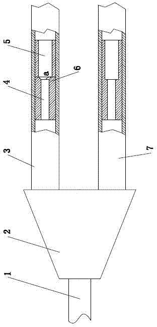
[0022] Such as figure 1 As shown, it is a two-way balanced flow distributor, including a splitter head 2, an inlet pipe 1, more than two connecting pipes and more than two resistance adjustment pipes; one end of the splitter head 2 is provided with an inlet port , the other end of the splitter head 2 is provided with more than two outlet ports, and each of the outlet ports communicates with the inlet port respectively; the outlet of the inlet pipe 1 communicates with the inlet port of the splitter head 2; the number of the connecting pipes The number of the outlet ports of the splitter head 2 is the same, and each connecting pipe is connected with the outlet port of the respective splitter head 2; In the connecting pipe and fastened, the outer wall of the resistance adjusting pipe is tightly matched with the inner wall of the connecting pipe; in this embodiment, the splitter head 2 has two outlet ports, so two connecting pipes and two resistance adjusting pipes are provided; ...

Embodiment 2

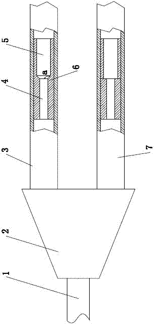
[0027] Such as figure 2As shown, a two-way balanced flow distributor includes a splitter head 2, an inlet pipe 1, more than two connecting pipes and more than two resistance adjustment pipes; one end of the splitter head 2 is provided with an inlet port for splitting The other end of the head 2 is provided with more than two outlet ports, and each outlet port is communicated with the inlet port respectively; the outlet of the inlet pipe 1 is communicated with the inlet port of the splitter head 2; The number of outlets of the head 2 is the same, and each connecting pipe is respectively connected with the outlet of the respective splitter head 2; the number of the resistance adjusting pipes is the same as that of the connecting pipes, and each resistance adjusting pipe is respectively arranged in the respective connecting pipes And fasten, the outer wall of the resistance adjusting pipe is sealed with the inner wall of the connecting pipe; in this embodiment, the splitter 2 ha...


PUM


Abstract

The invention relates to a bidirectional balanced flow distributor. The bidirectional balanced flow distributor is characterized by comprising a flow splitting head, an inlet pipe, more than two connecting pipes and more than two resistance adjusting pipe, wherein an inlet end is arranged at one end of the flow splitting head while more than two outlet ends are arranged at the other end of the flow splitting head; each outlet end is respectively communicated with the inlet end; the outlet of the inlet pipe is communicated with the inlet end of the flow splitting head; the connecting pipes are as many as the outlet ends of the flow splitting head; each connecting pipe is respectively communicated with the outlet end of respective flow splitting head; the resistance adjusting pipes are as many as the connecting pipes; each resistance adjusting pipe is respectively arranged in respective connecting pipe and is fastened; the outer wall of each resistance adjusting pipe is matched with the inner wall of each connecting pipe in a sealing manner; each resistance adjusting pipe comprises more than two sections of short pipes with different inner pipe diameters; and the short pipes are arranged sequentially according to the size of the inner pipe diameters and are mutually connected in series to form a variable-diameter bidirectional throttling short pipe. The bidirectional balanced flow distributor has the advantages of not only realizing balanced distribution of a flow in each branch of an indoor heat exchanger when an air conditioner runs for refrigeration, but also realizing balanced distribution of the flow when the air conditioner runs for heating through a simple structure, and solving the problem of unbalanced distribution of the flow in each branch of the heat exchanger well when the conventional air conditioner runs for heating.

Description

technical field [0001] The patent of the present invention relates to a flow distribution technology of a refrigeration system, especially a bidirectional balanced flow distributor technology in a cooling and heating air conditioner refrigeration system that performs cooling and heating operations, that is, a bidirectional balanced flow distributor. Background technique [0002] The indoor heat exchanger of the air conditioner has a long pipeline, and the resistance of the refrigerant flowing through the pipeline is relatively large, which affects the cooling effect; in order to reduce the resistance of the pipeline, the current method is to use a split flow method, that is, at the entrance of the indoor heat exchanger Install a flow distributor to divide the indoor heat exchanger into multiple branches in parallel. Since the length and flow of each branch are reduced, the resistance of the pipeline is reduced. However, there is also a problem when using the shunt technology...

Claims


Application Information

Patent Timeline
Patent Type & Authority Applications(China)
IPC IPC(8): F25B41/00F25B41/42
Inventor 陈学锋徐言生吴治将綦尤训胡明军宋林娜丁国良
Owner GUANGZHOU WEIJIN AIR CONDITIONER SCI & TECH
Why Eureka
Try Eureka