

Switching method and electronic equipment
A technology of electronic equipment and switching instructions, applied in the direction of data processing power supply, etc., can solve the problems of complex operation and can not be realized quickly
- Summary
- Abstract
- Description
- Claims
- Application Information
AI Technical Summary
Problems solved by technology
Method used
Image

Examples
no. 1 example
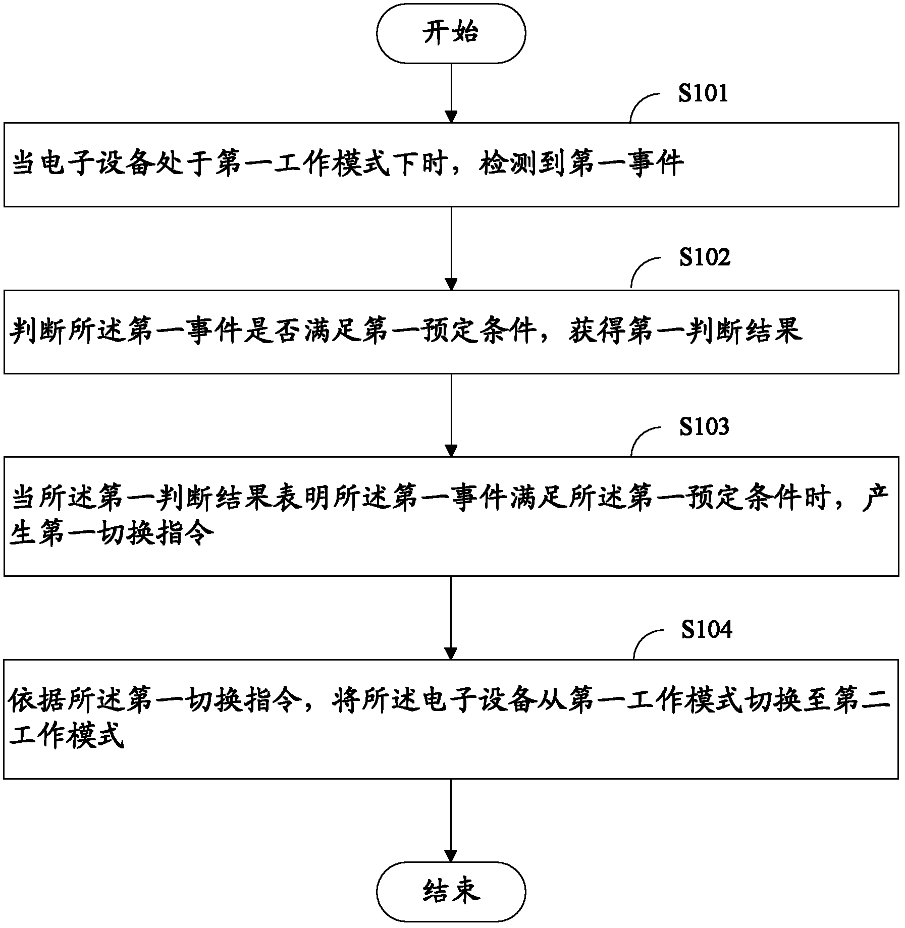
[0122] First, refer to figure 1 A display method according to a first embodiment of the present invention is described.
[0123] The handover method 100 according to the first embodiment includes:
[0124] Step S101: When the electronic device is in the first working mode, a first event is detected, wherein, in the first working mode, the first hardware system is in the first working state, so The second hardware system is in the fourth working state, and the operating system of the electronic device runs based on the first hardware system.
[0125] In this step, it is assumed that the electronic device is currently in the first working mode, and in the first working mode, the first hardware system is in the first working state, and the second hardware system is in the first working state. Four working states, the operating system of the electronic device runs based on the first hardware system. That is to say, in the first working mode of the electronic device, the first h...
no. 2 example
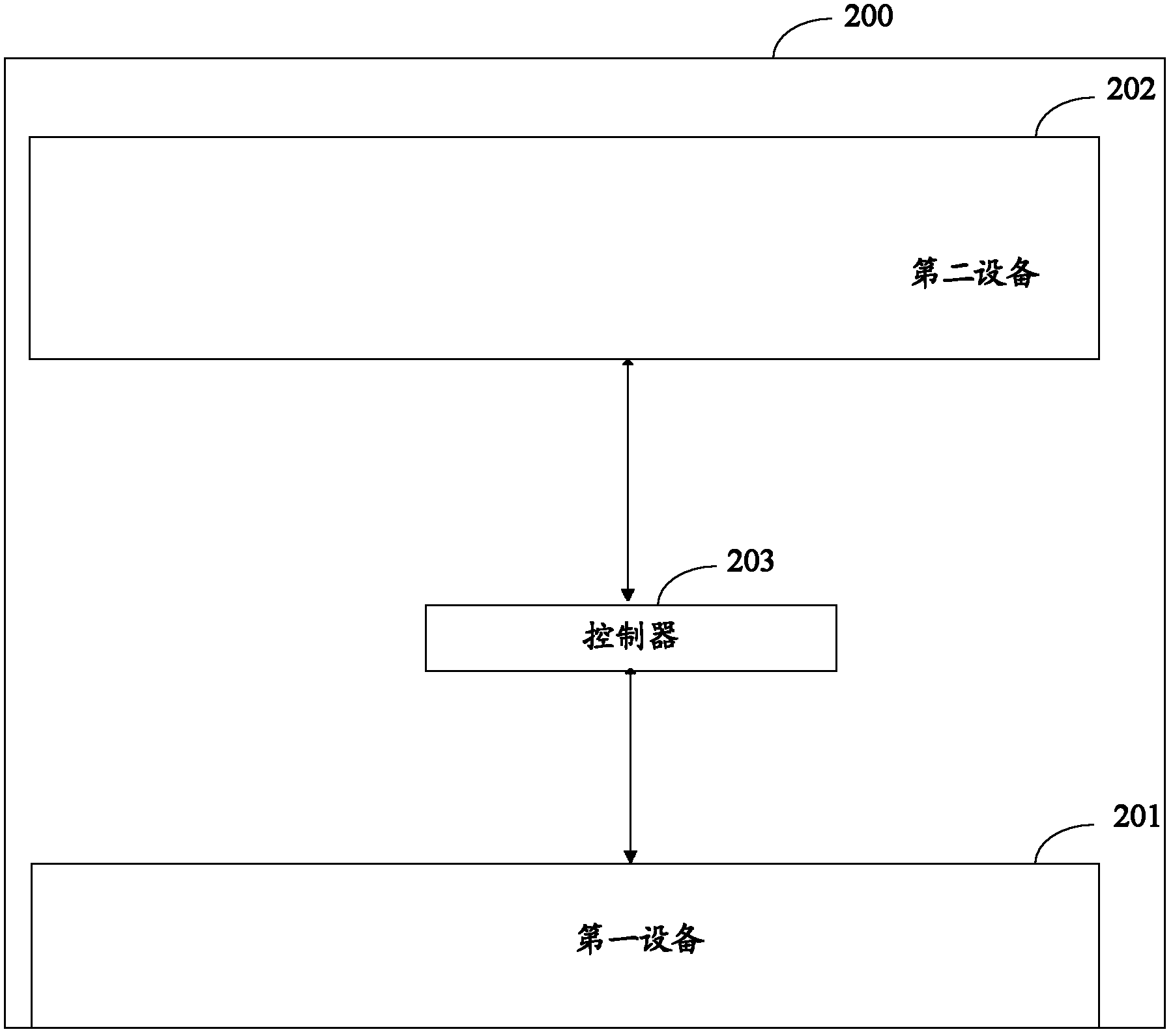
[0192] Next, refer to image 3 An electronic device according to a second embodiment of the present invention is described.
[0193] image 3 is a block diagram of an electronic device 300 according to a second embodiment of the present invention.
[0194] The electronic device 300 according to the third embodiment has at least a first working mode and a second working mode, including:
[0195] A first hardware system 301, the first hardware system 301 has a first working state and a second working state, the first power consumption of the first hardware system 301 in the first working state is greater than that of the first hardware system 301 second power consumption in the second working state, the first hardware system 301 includes a controller 303; and
[0196] The second hardware system 302, the second hardware system 302 is not exactly the same as the first hardware system 301, the second hardware system 302 has a third working state and a fourth working state, the s...
no. 3 example
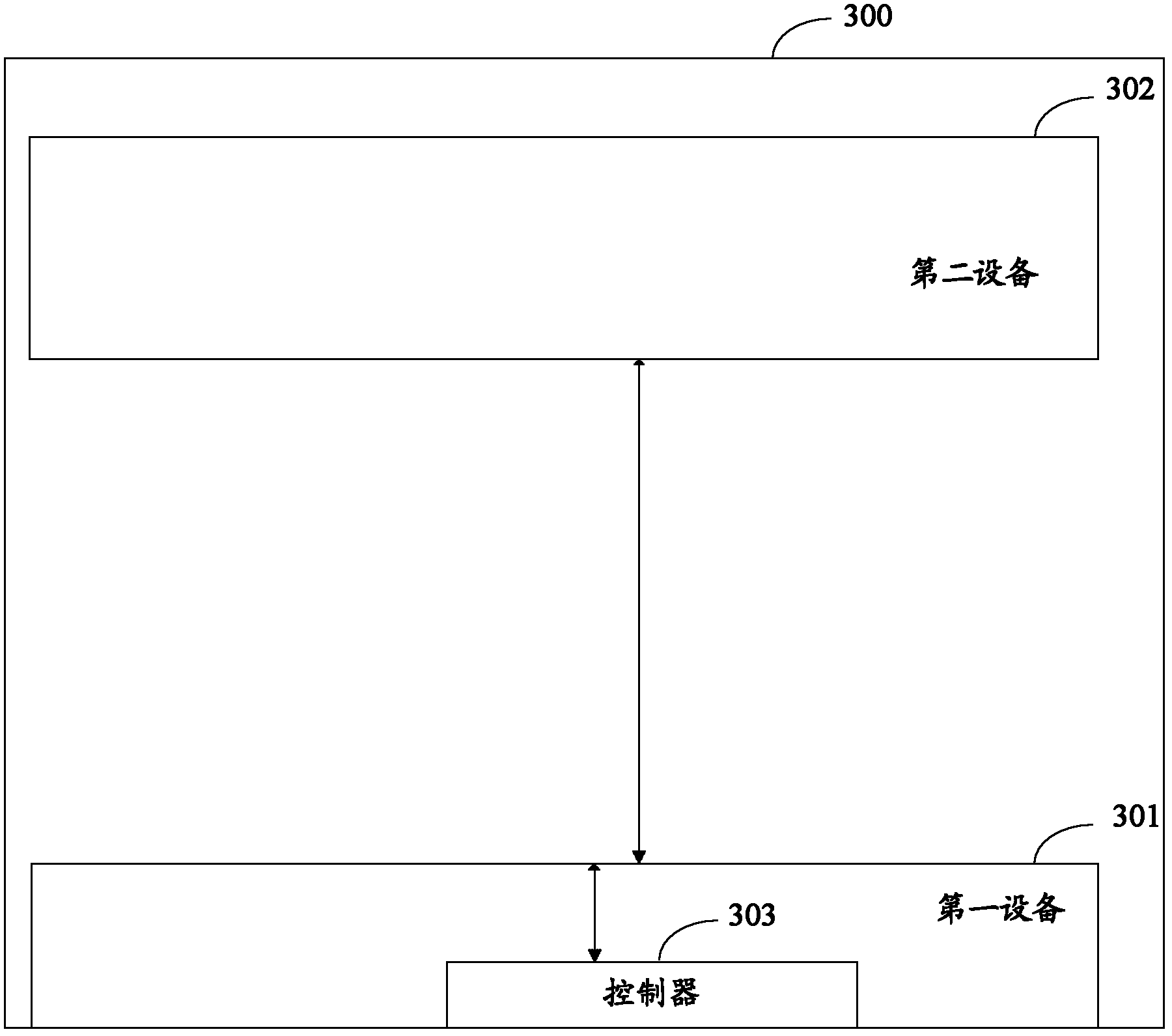
[0204] Next, refer to Figure 4 An electronic device according to a third embodiment of the present invention is described.
[0205] Figure 4 is a block diagram of an electronic device 400 according to a third embodiment of the present invention.
[0206] The electronic device 400 according to the third embodiment of the present invention has at least a first working mode and a second working mode, including:
[0207] A first hardware system 401, the first hardware system 401 has a first working state and a second working state, the first power consumption of the first hardware system 401 in the first working state is greater than that of the first hardware system 401 second power consumption in the second working state; and
[0208] The second hardware system 402, the second hardware system 402 is not exactly the same as the first hardware system 401, the second hardware system 402 has a third working state and a fourth working state, the second hardware system 402 The t...
PUM
 Abstract
Description
Claims
Application Information