Linear motor for pump

A technology for linear motors and pumps, applied in electrical components, electromechanical devices, electric components, etc., can solve the problems of limited effective thrust, consumption, and large inertial force of linear motors, and achieve continuous thrust and work efficiency. Simple, high speed and acceleration effects

Inactive Publication Date: 2013-07-17
BEIJING UNIV OF TECH
View PDF7 Cites 13 Cited by
  • Summary
  • Abstract
  • Description
  • Claims
  • Application Information

AI Technical Summary

Problems solved by technology

The mover of the above two linear motors is the primary coil, and its moving parts still con

Method used


Image

  • Linear motor for pump
  • Linear motor for pump
  • Linear motor for pump

Examples


Embodiment Construction

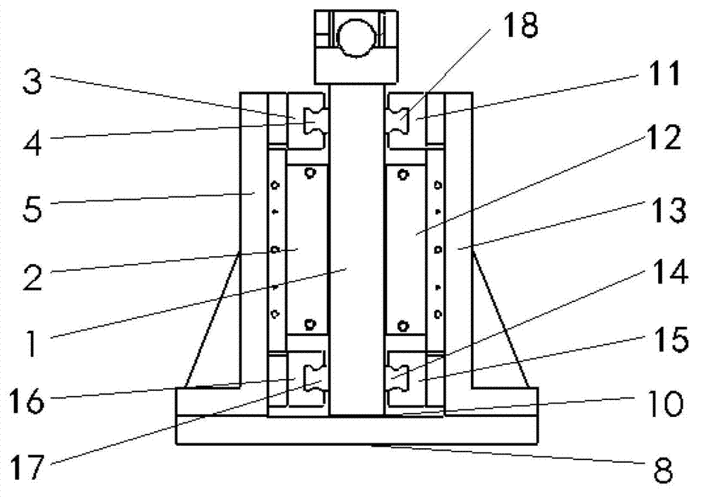
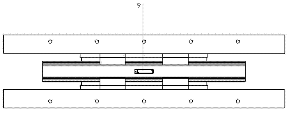
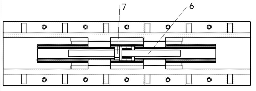
[0022] Such as Figure 1-3 Shown, a kind of pump linear motor of the present invention, its specific embodiment is as follows:

[0023] Including the stator and the mover 1, the linear motor adopts a moving iron symmetrical structure, that is, the two primary coils 2 and 12 are used as the stator, the permanent magnet yoke group is used as the mover 1, and the two primary coils 2 and 12 are symmetrically arranged on the mover 1 The two sides of the primary coils 2 and 12 are connected to the UVW three-phase alternating current to generate a traveling wave magnetic field, and the mover 1 generates a thrust relative to the stator under the combined action of the two traveling wave magnetic fields; among them, the two primary The coils 2 and 12 are respectively installed on the stator mounting plates 5 and 13 on both sides of the mover 1, and the upper and lower ends of the two primary coils 2 and 12 are respectively provided with sliders 3, 11, 15 and 16, and the slider 3 . Th...


PUM


Abstract

The invention relates to a linear motor for a pump. The linear motor adopts a moving-iron type symmetrical structure, and two groups of coils serve as stators and are symmetrically distributed on two sides of a permanent magnet active cell. The stator coils of the motor is connected to a three-phase alternating current power supply and produces a specific traveling wave magnetic field, the active cell produces axial pushing force relative to the stators under the effect of the traveling wave magnetic field, the direction of pushing forced produced by two stators and the active cell are consistent under the effect of the traveling wave magnetic field, and the active cell directly acts energy on a plunger rod to enable the plunger rod to perform reciprocating motion along a guide rail. The linear motor for the pump achieves output of large pushing force, improves the effective pushing force and work efficiency and is suitable for driving of a plunger pump with high and medium voltage and large flow.

Description

technical field [0001] The invention relates to a motor, in particular to a linear motor for a pump, which belongs to the field of motor control. Background technique [0002] In order to achieve the requirements of constant flow and no pressure fluctuation of reciprocating pumps, several newly developed reciprocating pumps have effectively improved some shortcomings of traditional reciprocating pump structures: cam mechanism reciprocating pumps, hydraulic drive reciprocating pumps. However, the constant flow reciprocating plunger movement of the cam mechanism has a flexible impact, the acceleration has a sudden change, and the cam mechanism at the power end is highly complex and easy to wear, and the reliability needs to be further improved. Therefore, the current constant flow reciprocating pump with the cam mechanism as the power end is still limited to medium and low pressure applications. , small flow and low power applications. The hydraulically driven reciprocating p...

Claims


Application Information

Patent Timeline
IPC IPC(8): H02K41/03H02K3/24
Inventor 聂松林董武涛赵君鑫廖伍举申凤梅张安庆
Owner BEIJING UNIV OF TECH
Why Eureka
Try Eureka