Motor-powered machine tool, in particular a hand-held machine tool

A hand-held machine tool and motor-driven technology, which is applied in the direction of motor tools, multi-purpose hand tools, manufacturing tools, etc., can solve the problems of restricting the shape of the top surface of the shell, and achieve the effect of simple structure, precise manufacturing, and simple manufacturing

Active Publication Date: 2013-07-17
ROBERT BOSCH GMBH
View PDF6 Cites 2 Cited by
  • Summary
  • Abstract
  • Description
  • Claims
  • Application Information

AI Technical Summary

Problems solved by technology

In addition, the shape of the top surface of the housing is limited, or other operating components must be arranged in other positions of the housing

Method used


Image

  • Motor-powered machine tool, in particular a hand-held machine tool
  • Motor-powered machine tool, in particular a hand-held machine tool
  • Motor-powered machine tool, in particular a hand-held machine tool

Examples


Embodiment Construction

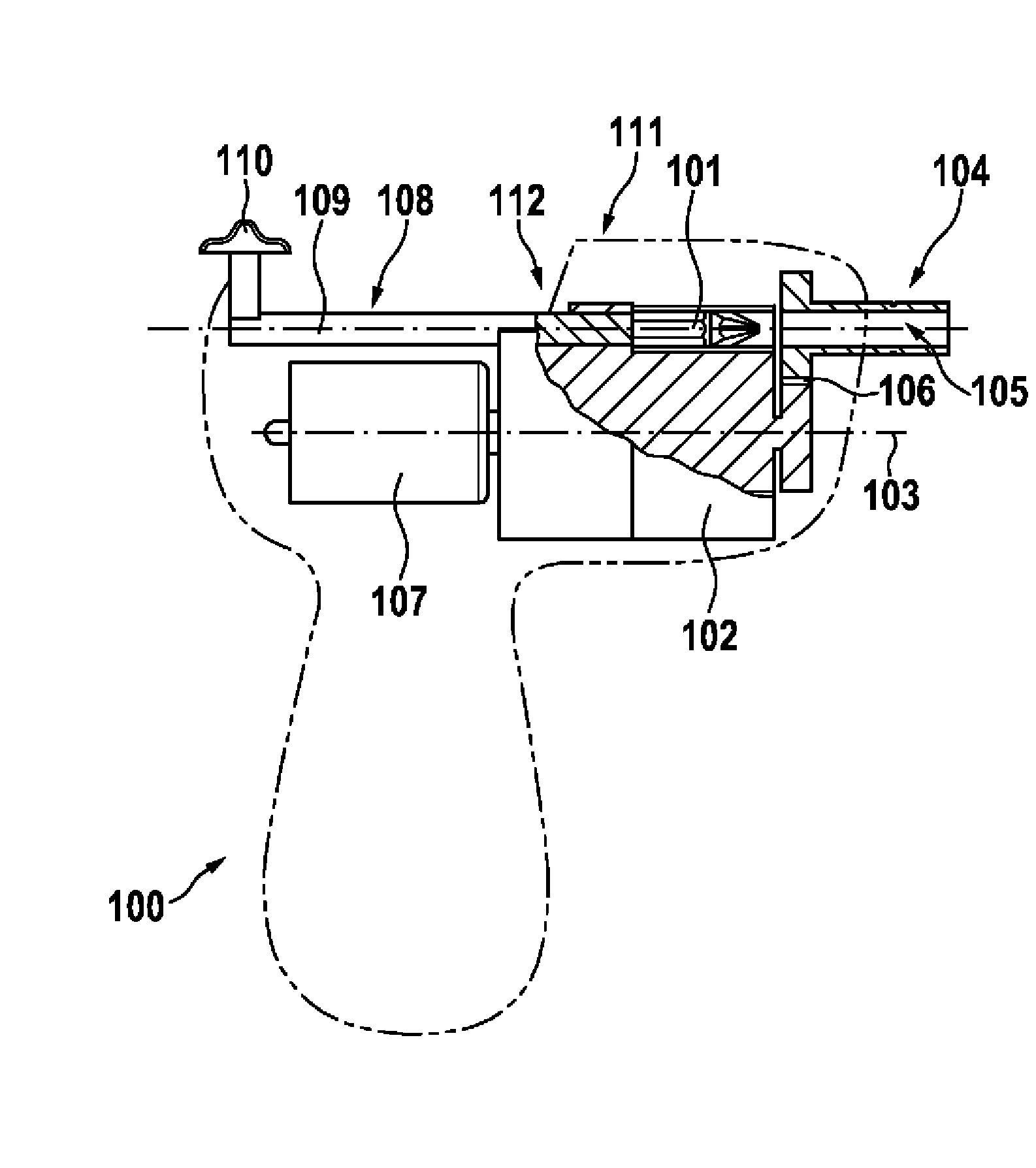
[0031] FIG. 1 shows a very simplified illustration of a motor-driven power tool 100 in the form of a hand power tool according to the prior art. The machine tool 100 is here designed in the form of a so-called "rotary screwdriver", which is suitable for handling various tools 101 in the form of rotary inserts. The tool 101 is arranged in a tool compartment of a revolver-style tool box 102 , not shown in FIG. 1 , wherein the tool box 102 is mounted rotatably in a longitudinal axis 103 . The machine tool 100 also has a tool chuck 104 which has a tubular region 105 into which a tool 101 to be used from a tool box 102 is inserted. To exchange for a new tool 101 , the tool chuck 104 is rotated centered on the empty tool chamber of the tool box 102 . The tool chuck 104 is connected to drive the tool 101 via a gear tooth 106 to a drive motor 107 , which generates a corresponding rotational movement of the tool chuck 104 , wherein the tool 101 is arranged in the tool chuck 104 in a n...


PUM


Abstract

The invention relates to a motor-powered machine tool (10), in particular a hand-held machine tool, comprising a drum-like tool-changing magazine (12) having tool chambers, which is arranged inside a housing (24), wherein in a change position one of the tool chambers of the tool-changing magazine (12) is aligned with a tubular tool holder (14; 54), and further comprising a sliding element (15) for sliding a tool (101) from the tool-changing magazine (12) into the tool holder (14; 54) and from the tool-changing magazine (12) back into the tool holder (14; 54), said sliding element being movable in a longitudinal direction of the tool holder (14; 54). According to the invention, the sliding element (15) is coupled with a gearbox system (20) comprising at least one toothed gear (18, 18a, 18b, 19, 19a, 19b), the rotational motion of which is translated into linear movement of the sliding element (15).

Description

technical field [0001] The invention relates to a motor-driven machine tool, in particular a hand-held machine tool, according to the preamble of claim 1 . Background technique [0002] Such a machine tool is known from DE 10 2006 059 688 A1 by the applicant. Known power tools have a roller tool box in which the tools are each arranged in a tool compartment. The tool box can be rotated on its longitudinal axis, so that the tool compartment can be aligned with the tubular connecting channel, via which the required tool can be pushed into the chuck of the power tool or brought back from the tool chuck to the tool compartment . For this purpose, a manually actuated sliding element is actuated, which is essentially pin-shaped and can be actuated by means of a handle which passes through the housing on its upper side. Due to the relatively long travel distances, the handle which is actuated by the operator requires a relatively long travel travel on the top side of the housing...

Claims


Application Information

Patent Timeline
Patent Type & Authority Applications(China)
IPC IPC(8): B25B21/00B25F5/02
CPCB25B23/06B25B21/00B25F5/029Y10T483/17Y10T483/1798Y10T483/1755Y10T483/1827B25F1/04B23Q3/15766
Inventor A.纳吉
Owner ROBERT BOSCH GMBH
Why Eureka
Try Eureka