
Combined chamber wall and heat exchanger

A technology for heat exchangers and cylinder walls, applied in the field of heat exchangers, can solve the problems of different, difficult to provide, increasing the demand for heat removal, etc.

Active Publication Date: 2013-07-17
HIETA TECH
View PDF7 Cites 4 Cited by
  • Summary
  • Abstract
  • Description
  • Claims
  • Application Information

AI Technical Summary

Problems solved by technology

Both of these factors increase the load on the heat exchanger and will increase the need to preheat air on the hot end and reject heat on the cold end
[0004] The second cause is a severe heat exchange imbalance between the low pressure combustion gas and the high pressure charge gas, and a similar but less severe imbalance in the cooler
However, it is difficult for these fins to provide a means to increase the heat transfer to a level sufficient to make a significant difference in efficiency

Method used


Image

  • Combined chamber wall and heat exchanger
  • Combined chamber wall and heat exchanger
  • Combined chamber wall and heat exchanger

Examples


Embodiment Construction

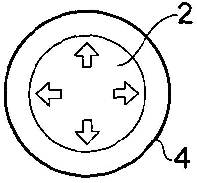
[0045] Figure 1 shows a prior art cylinder, such as that used in a reciprocating piston engine. The cylinder includes charge gas 2 which must be contained by cylinder walls 4 . The cylinder wall 4 is solid and the thickness of the cylinder wall 4 is such that it is strong enough to contain the charge gas 2 .

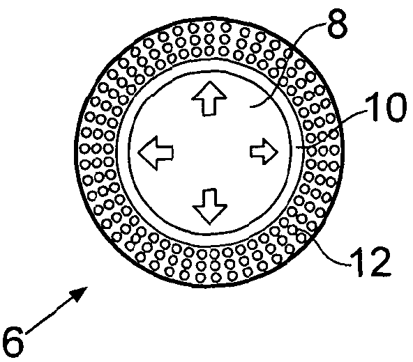
[0046] figure 2 Cylinder 6 for a reciprocating piston engine is shown. Cylinder 6 contains charge gas 8 . The walls of the cylinder 6 accommodate a solid part 10 and a heat exchanger part 12 . The heat exchanger section houses a plurality of conduits forming an array of conduits. The array of conduits is in fluid communication with the exterior of the cylinder 6 . Accordingly, heat may be removed from or sent to the cylinder 6 via fluid flowing through these conduits within the heat exchanger portion 12 .

[0047] exist figure 2 As can be seen in Fig. 1, the solid portion 10 of the wall is thinner than the cylinder wall 4 of the embodiment of Fig. 1 . Because add...


PUM


Abstract

An apparatus having a wall configured to serve as at least part of a chamber for containing a charge fluid is provided. The wall includes a heat exchanger portion integrally formed with the wall. The heat exchanger portion includes an array of conduits passing therethrough and providing fluid communication with outside of the heat exchange portion. The heat exchange portion is configured to contribute strength to the wall so as to provide containment of the charge fluid.

Description

technical field [0001] The invention relates to the field of heat exchangers. Background technique [0002] Small and efficient heat engines for carbon-efficient applications are increasingly required in the energy conservation and renewable energy industries. These applications include micro cogeneration, concentrated solar power and combined heat and power, heat pumps, electricity from waste and waste heat, and electricity from small solid biomass systems. For many years, the Stirling engine was the prime mover of choice, largely due to the high theoretical efficiency of the Stirling cycle. In practice, however, technical problems have prevented this theoretical efficiency from being achieved in high proportions, and the costs remain high. As a result, the Stirling engine has not been commercialized on a large scale. [0003] One reason for the lack of commercialization of the Stirling engine is that due to the reversal of the out-of-phase reciprocating motion of the pi...

Claims


Application Information

Patent Timeline
IPC IPC(8): F28D1/06F28F7/02B22F3/105F02F1/10F02G1/055
CPCF28F7/02B22F3/1055F28D1/06B22F2003/1056B22F7/004B21D53/02F02G2256/04F02G1/055Y10T29/49364Y02P10/25B22F10/28B22F10/38F02F1/10B22F10/00B33Y80/00
Inventor 德拉蒙德·沃特森·希斯洛普
Owner HIETA TECH
Learn More