Piezoelectric ultrasonic atomizer

A piezoelectric ultrasonic and nebulizer technology, applied in the field of nebulizers, can solve problems such as low energy utilization rate, reduced atomization effect, and shortened service life of the nebulizer, so as to improve energy utilization rate and reduce use cost , the effect of prolonging the service life

Inactive Publication Date: 2013-07-24
NANJING CHANGHUI ELECTROMECHANICAL TECH
View PDF5 Cites 2 Cited by
  • Summary
  • Abstract
  • Description
  • Claims
  • Application Information

AI Technical Summary

Problems solved by technology

For example, when the input energy of the atomizer is given, the design of atomization hole spacing x is too small, and the number of atomization holes n is too large, so that the energy allocated to each atomization hole is reduced, and the atomization effect is reduced
At the same time, because the atomization hole spacing x is too small, serious stress concentration and stress fatigue will occur in the atomization hole distribution area, resulting in shortened service life of the atomizer and relatively increased use cost of the atomization device; on the contrary, when the atomization hole spacing x If the design is too large and the number of atomization holes n is too small, the number of holes participating in the atomization process will be too small, the energy utilization rate will be low, and the atomization effect will not be ideal

Method used


Image

  • Piezoelectric ultrasonic atomizer
  • Piezoelectric ultrasonic atomizer
  • Piezoelectric ultrasonic atomizer

Examples


Embodiment Construction

[0020] The present invention will be further described below in conjunction with the accompanying drawings.

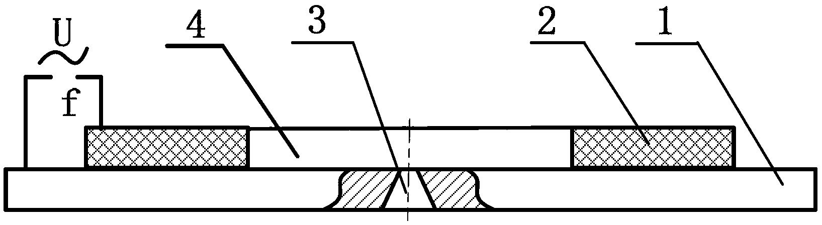
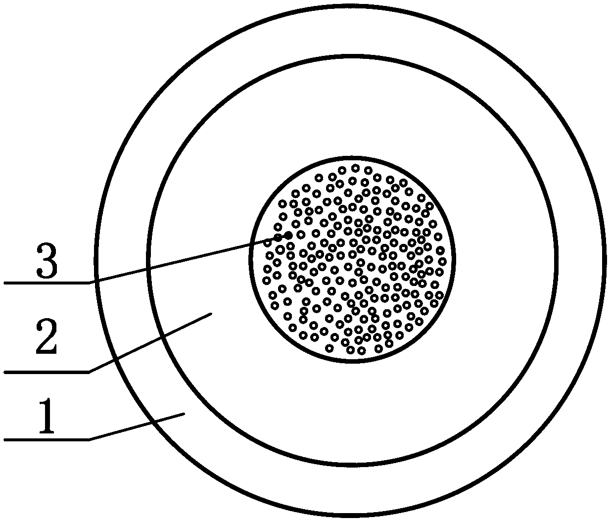
[0021] First, combine figure 1 and figure 2 Describe the working principle of piezoelectric ceramic atomizer. There is an area in the central area of ​​the metal diaphragm 1 that is densely distributed with tiny atomization holes 3, and outside the distribution area of ​​the atomization holes 3 is a piezoelectric ceramic ring piece 2, and the metal diaphragm 1 and the piezoelectric ceramic ring piece 2 are respectively connected to the positive and negative points of the AC power supply. The poles are connected, the input voltage value is U, and the input AC frequency is f. According to the energy calculation formula of alternating current, the energy E supplied by alternating current is proportional to the square of the voltage value U and the input frequency f, that is, E=kUf 2 (where k is a coefficient). In actual work, the input voltage value U is given, so it...


PUM


Abstract

The invention discloses a piezoelectric ultrasonic atomizer, which comprises a metal diaphragm and a piezoelectric ceramic ring sheet in mutual connection, wherein the outer diameter of the piezoelectric ceramic ring sheet is smaller than or equal to the diameter of the metal diaphragm, a group of atomization holes are formed in the metal diaphragm and are positioned in the through hole region of the piezoelectric ceramic ring sheet, the longitudinal cross sections of the atomization holes in the group of atomization holes are in a cone shape, the opening diameter of one end facing the through hole is smaller than the opening diameter of the other end, and in addition, the spaces of any three adjacent atomization holes are identical or similar. The atomization holes meet the requirement that x is smaller than 1.2d1 but greater than 0.7d1, and in addition, the area of the atomization hole region meets a formula that A1=(30 percent to 45 percent)S, wherein d1 is the diameter of the opening of the atomization hole back to the through hole, x is the space of any three adjacent atomization holes, A1 is the total area of the atomization hole back to the through hole, and S is the distribution region area of the atomization holes. The piezoelectric ultrasonic atomizer has the advantages that through the arrangement of the atomizer, the problem of unstable atomization effect caused by design blindness of the atomizer is avoided, in addition, the service life of the atomizer is relatively prolonged, and the use cost is reduced.

Description

technical field [0001] The invention relates to an atomizer, which is used for transporting and transporting liquid, in particular to an atomizer which utilizes piezoelectric ceramics for ultrasonic atomization. Background technique [0002] The process of breaking up liquid into small mist droplets is called atomization, which is actually an energy conversion process that converts input electrical energy into mechanical energy of small droplets and simultaneously generates other forms of energy, such as heat energy. [0003] Existing piezoelectric ceramic ultrasonic nebulizer (as attached figure 1 And attached figure 2 As shown), the distribution parameters and arrangement of the atomizing holes on the metal diaphragm lack certain regularity, and there is a certain blindness in the design of the atomizing holes in the atomizer, which inevitably makes the final atomization of the atomizer There is a certain degree of instability in the work effect. For example, when the ...

Claims


Application Information

Patent Timeline
Patent Type & Authority Applications(China)
IPC IPC(8): B05B17/04B05B17/06
Inventor 张建辉
Owner NANJING CHANGHUI ELECTROMECHANICAL TECH
Why Eureka
Try Eureka