
Automatic pipe cutting device

A pipe cutting device and automatic technology, applied in the direction of metal processing, etc., can solve the problems of only single machine operation, not suitable for automatic production line matching, automatic feeding and discharging, etc., to achieve the effect of meeting the needs of automation

Inactive Publication Date: 2013-07-24
GOLD HONG YE PAPER
View PDF5 Cites 3 Cited by
  • Summary
  • Abstract
  • Description
  • Claims
  • Application Information

AI Technical Summary

Problems solved by technology

Although this method has higher efficiency and better precision, it can only be operated by a single machine, and cannot automatically feed and discharge materials, so it is not suitable for matching with automatic production lines.

Method used


Image

  • Automatic pipe cutting device
  • Automatic pipe cutting device
  • Automatic pipe cutting device

Examples


Embodiment Construction

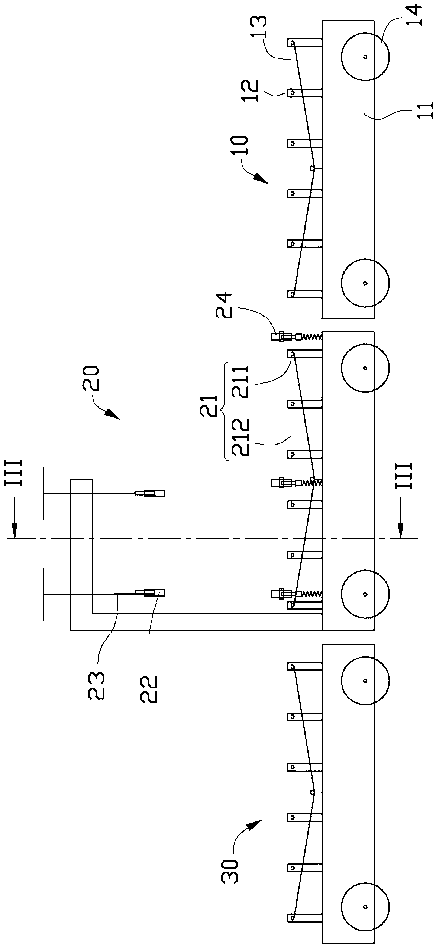
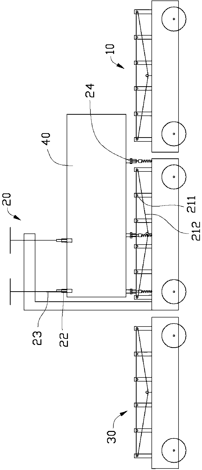
[0024] Please refer to figure 1 with figure 2 , The automatic pipe cutting device according to one embodiment of the present invention includes an incoming material mechanism 10 , a material cutting mechanism 20 and a material discharging mechanism 30 . The incoming material mechanism 10 is used to transport the pipe material 40 to the material cutting mechanism 20 . The material cutting mechanism 20 adjusts the position of the pipe material 40 and executes the pipe cutting operation. The discharging mechanism 30 is used for conveying the cut pipe 40 out. The incoming material mechanism 10 is located upstream of the material cutting mechanism 20 , and the material discharging mechanism 30 is located downstream of the material cutting mechanism 20 .

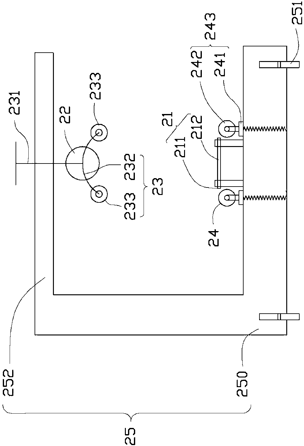
[0025] Please also refer to image 3 , the material cutting mechanism 20 includes a main frame 25, a pipe feeding device 21 for adjusting the position of the pipe material 40, a pipe cutting knife 22 for performing a pipe cut...


PUM


Abstract

The invention provides an automatic pipe cutting device which is used for cutting a tubular product. The automatic pipe cutting device comprises a material feeding mechanism, a material cutting mechanism and a material discharging mechanism, wherein the material feeding mechanism is used for conveying the tubular product; the material cutting mechanism is arranged in a downstream direction of the material feeding mechanism and is used for adjusting the position of the tubular product and cutting the tubular product; the material cutting mechanism comprises a pipe conveying device, supporting devices arranged at the two sides of the pipe conveying device, and a pipe pressing device and a pipe cutter arranged above the pipe conveying device, wherein the supporting devices, the pipe pressing device and the pipe cutter can move relative to the pipe conveying device; and the material discharging mechanism is arranged in the downstream direction of the material cutting mechanism and is used for conveying the tubular product cut by the material cutting mechanism. The automatic pipe cutting device disclosed by the invention can realize operation with higher automation from processes of feeding, fixing and cutting to the process of discharging, so that the automatic pipe cutting device can be matched with an automatic production line and the automation requirements of a modern manufacturing industry can be met.

Description

technical field [0001] The invention relates to a pipe material cutting device, in particular to an automatic pipe cutting device. Background technique [0002] In industrial production, climbing automatic pipe cutting machines and turning automatic pipe cutting machines are usually used to cut large pipe diameters, such as pipes with pipe diameters greater than 50mm. But both types of pipe cutters have certain disadvantages. [0003] The crawling automatic pipe cutting machine uses a cutter to crawl around the pipe for a week, and cut the pipe while crawling. However, the crawling performance is poor. When the cutter is crawling, it often idles on the pipe wall, causing the crawling to stop and the cutting to be interrupted. Therefore, it is usually necessary to use external force to complete the work. And after cutting around the pipe wall for a week, the incisions cannot overlap, and the incision accuracy is low. In addition, this kind of pipe cutting machine involves ...

Claims


Application Information

Patent Timeline
IPC IPC(8): B26D1/14B26D7/06B26D7/02
Inventor 朱三明高鹤翔杨晓静
Owner GOLD HONG YE PAPER
Learn More