Microchip fluid control mechanism

一种控制机构、控制方法的技术,应用在分析材料、仪器等方向,达到简单流路结构的效果

Active Publication Date: 2013-07-24
NEC CORP
View PDF8 Cites 0 Cited by
  • Summary
  • Abstract
  • Description
  • Claims
  • Application Information

AI Technical Summary

Problems solved by technology

[0009] In addition, the prior art shown in Patent Document 3 must use non-compressible media and cannot use compressive media

Method used


Image

  • Microchip fluid control mechanism
  • Microchip fluid control mechanism
  • Microchip fluid control mechanism

Examples


no. 1 approach

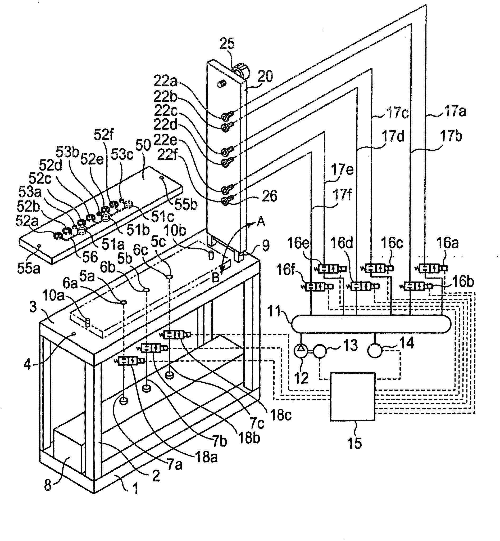
[0032] figure 1 It is a cross-sectional perspective view showing the structure of an apparatus for reacting a chemical sample using the microchip according to the first embodiment of the present invention.

[0033] The stand 1 is provided with a table 3 via the pillar 2, and the table 3 is further provided with discarding holes 5a, 5b, 5c and pipes 7a, 7b, 7c whose peripheries are sealed by O-rings 6a, 6b, 6c. Furthermore, the disposal holes 5a, 5b, and 5c are connected to the disposal tank 8 provided in the rack 1 via the disposal electromagnetic valves 18a, 18b, and 18c. Furthermore, pins 10a and 10b for guiding the microchip 50 to a predetermined position are provided in a convex shape on the upper surface of the table 3 . Moreover, a cover 20 is provided on the table 3 so as to be rotatable in directions A and B via a hinge 9, wherein the cover 20 has fastening screws 25 and pressurizing holes 22a, 22b which pass through by sealing the surroundings with an O-ring 26, 22c...


PUM


Abstract

Compressed gas is supplied from above to a specimen vessel having an open top. Transfer channels to reaction vessels are provided under a microchip and transfer channels extending from the reaction vessels are provided on the microchip. Transfer element is provided outside the microchip so as to supply the compressed gas from a member (cover) holding the microchip.

Description

[0001] This application is a divisional application, the application number of its parent application is: 200880007064.7, the filing date: 2008.3.4, the name of the invention: microchip fluid control mechanism. technical field [0002] The present invention relates to a fluid control mechanism and a fluid control method of a microchip, in particular to a plurality of reaction tanks and sample tanks for reaction / mixing / separation / analysis of chemical samples, or gene analysis, etc. A micro-analysis chip that connects the flow path between the reaction tank and the sample tank. Background technique [0003] In recent years, as recorded in Zhuangzi Xiyi's "Biochemical Microchemical Analysis System Micromachine Technology" (non-patent document 1) or JP-A-2002-214241 (patent document 2), in microreactors, microarrays and known as " There are more and more studies on gene analysis by reacting samples or liquid samples on a tiny chip of "Lab on a chip", and studies have been made o...

Claims


Application Information

Patent Timeline
Patent Type & Authority Applications(China)
IPC IPC(8): G01N35/08
CPCG01N35/08
Inventor 麻生川稔萩原久平松彻
Owner NEC CORP
Why Eureka
Try Eureka