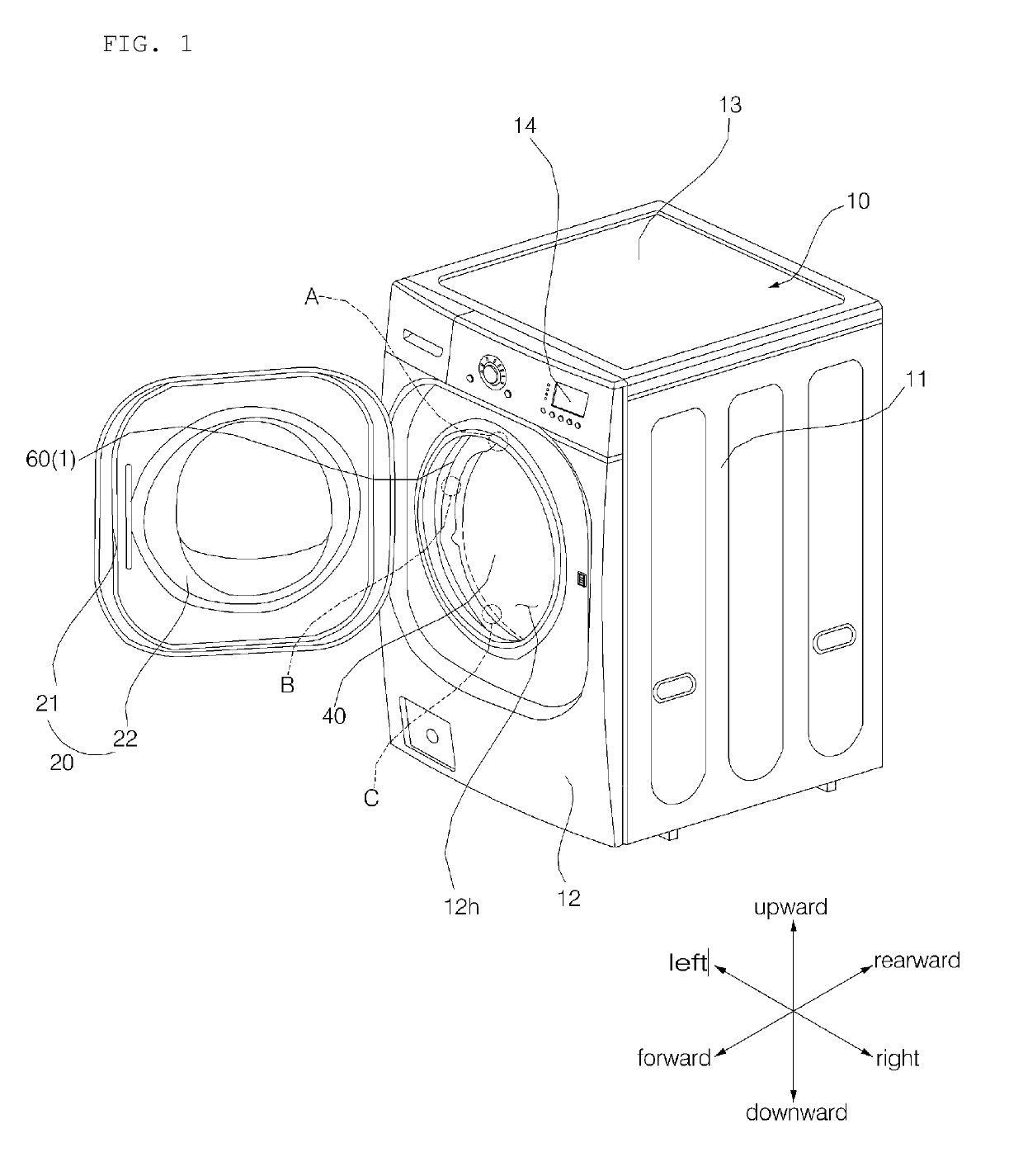
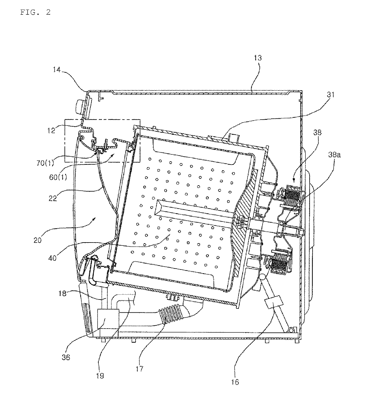
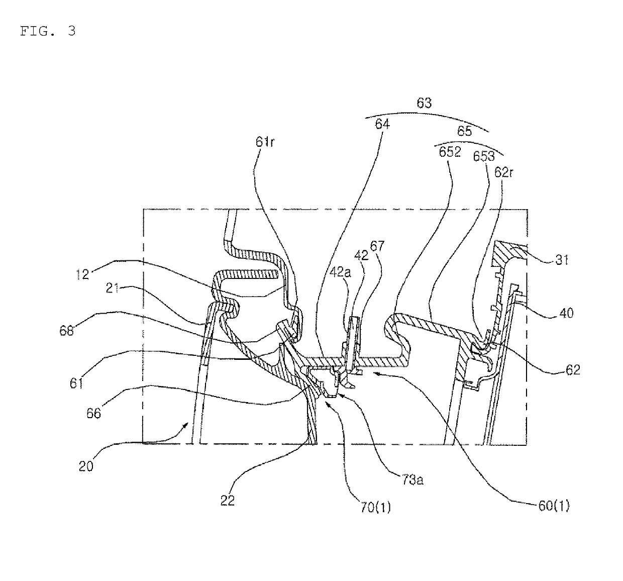
Washing machine

a technology of washing machine and gasket, which is applied in the field of washing machines, can solve the problems of inability to evenly wet laundry, remarkable improvement of performance cannot be expected with a conventional structure, etc., and achieves the effects of easy installation in the gasket, easy separation from the gasket, and simplified flow path structur

Active Publication Date: 2019-10-31
LG ELECTRONICS INC
View PDF0 Cites 4 Cited by
  • Summary
  • Abstract
  • Description
  • Claims
  • Application Information

AI Technical Summary

Benefits of technology

[0042]In the washing machine of the present invention, first, an annular guide pipe for guiding circulating water to be sprayed into the drum is installed in a gasket, and the guide pipe is firmly fixed to the gasket, so that even if vibration is generated due to rotation of a drum, there is an effect that the guide pipe is not easily separated from the gasket.
[0043]Second, the water discharged from a tub is sprayed into the drum in various directions at three or more different heights, so that three-dimensional washing can be accomplished.
[0044]Third, since the water discharged from the tub is guided to a plurality of nozzles through a single common flow path, the flow path structure is simplified.
[0045]Fourth, by forming the common flow path in an annular shape, it is easy to install in the gasket.
[0046]Fifth, by supplying water to the nozzles by using a pump capable of controlling the flow rate (or the speed, the number of revolutions), there is an effect that the flow rate, the pressure (or intensity) of the water sprayed through the nozzles, or the range which the sprayed water can reach can be varied.
[0047]Sixth, there is an effect that the water sprayed through the nozzle can reach the deep position of the inside of the drum in comparison with the conventional art.

Problems solved by technology

However, since such a conventional washing machine usually includes a single or two nozzles, the direction of spraying through a nozzle is restricted, and thus the laundry cannot not be wet evenly.
In particular, in recent years, although new technologies for controlling the rotation of the drum have been developed in order to impart variety to the flow of laundry put into the drum, there is a limit in that a remarkable improvement in performance cannot be expected with a conventional structure.

Method used


Image

  • Washing machine
  • Washing machine
  • Washing machine

Examples


second embodiment

[0175]FIG. 15 shows an assembly of a gasket and a circulating water spraying apparatus according to the present invention. FIG. 16 is a perspective view of the circulating water spraying apparatus shown in FIG. 15, and enlarged views of an upper nozzle and a cross-sectional view of connection pipe. Hereinafter, the same reference numerals are assigned to the same components as those of the above-described embodiment, and the description thereof will be made as described above.

[0176]According to a second embodiment of the present invention, the gasket 60(2) may be provided with an accommodating groove 64a for accommodating the guide pipe 71. It is preferable that the accommodating groove 64a is formed in the flat portion 64. A part of the flat portion 64 is protruded to the outside of the gasket 60(2), and the accommodating groove 64a may be formed on the inner circumferential surface of the flat portion 64. The accommodating groove 64a may be formed to have an annular shape, but pre...

third embodiment

[0178]FIG. 17 is a cross sectional view showing a structure in which a circulating water spraying apparatus 70(1) is installed in a gasket 60(3) according to the present invention. Referring to FIG. 17, the circulating water spraying apparatus 70(1) may be configured such that the guide pipe 71 and the nozzles 73a, 73b(1), 73b(2), 73c(1), 73c(2) are integrated. The gasket 60(3) may include a cylindrical accommodating portion 640 protruded from the inner circumferential surface of the flat portion 64 and extending along the circumference.

[0179]A circulating water spraying apparatus 70(1) is accommodated inside the accommodating portion 640. An opening portion 69h is formed in the accommodating portion 640 at positions corresponding to the outlets of the respective nozzles 73a, 73b(1), 73b(2), 73c(1), and 73c(2) respectively, so that the circulating water is sprayed into the drum 40 through the opening 69h.

[0180]The circulating water spraying apparatus 70(1) may be embedded in the ga...

fourth embodiment

[0184]FIG. 18 shows an assembly of a gasket and a circulating water spraying apparatus according to the present invention. FIG. 19 shows the circulating water spraying apparatus shown in FIG. 18. FIG. 20 is a cross-sectional view of an upper nozzle in a state where the circulating water spraying apparatus shown in FIG. 18 is installed in the gasket.

[0185]Referring to FIGS. 18 to 20, the circulating water spraying apparatus includes a guide pipe 71, an upper nozzle 730(1) supplied with water from the guide pipe 71, a pair of intermediate nozzles 730(2) and 730(5), and a pair of lower nozzles 730(3) and 730(4).

[0186]The guide pipe (71) is branched to both sides from the opening into which the circulating water flows and forms an annular flow path. The portion forming the annular flow path 71 is divided into a plurality of sections (711, 716), 712, 713, 714 and 715, and the nozzles 730(1), 730(2), 730(3), 730(4), and 730(5) are connected between adjacent sections.

[0187]The nozzles 730(...


PUM


Abstract

A washing machine includes: a casing, a tub, a drum, a cylindrical gasket connecting an input port of the casing to an opening of the tub, a pump configured to circulate water discharged from the tub; a guide pipe fixed to the gasket configured to guide water supplied from the pump, and nozzles configured to spray water from the guide pipe into the drum. The nozzles include an upper nozzle configured to spray water downward, intermediate nozzles disposed below the upper nozzle in both left and right sides and configured to spray water downward while spraying water deeper into the drum than the upper nozzle, and lower nozzles disposed above the inflow port, disposed below the intermediate nozzles in both left and right sides based on the inflow port and configured to spray water upward.

Description

TECHNICAL FIELD[0001]The present invention relates to a washing machine having a nozzle for discharging water, which is discharged from a tub and circulated along a circulation pipe, into a drum.BACKGROUND ART[0002]Generally, a washing machine is an apparatus that separates contaminants from clothing, bedding, and the like (hereinafter, referred to as “laundry”) by using a chemical decomposition of water and detergent and a physical action such as friction between water and laundry.[0003]Such a washing machine includes a tub containing water and a drum rotatably installed in the tub to receive the laundry. A recent washing machine is configured to circulate water discharged from the tub by using a circulation pump, and to spray the circulated water into the drum through a nozzle. However, since such a conventional washing machine usually includes a single or two nozzles, the direction of spraying through a nozzle is restricted, and thus the laundry cannot not be wet evenly.[0004]In ...

Claims


Application Information

Patent Timeline
Patent Type & Authority Applications(United States)
IPC IPC(8): D06F37/06D06F33/02D06F39/12D06F37/22D06F37/30D06F39/08
CPCD06F33/02D06F37/22D06F39/12D06F37/06D06F37/30D06F39/08D06F37/266D06F39/083D06F33/00
Inventor JUNG, HWANJINIM, MYUNGHUNLEE, JUNGHOONWOO, KYUNGCHULKIM, HYUNDONG
Owner LG ELECTRONICS INC
Why Eureka
Try Eureka