
Electric energy storing device

An electrical energy storage and device technology, applied in electrical components, battery pack parts, hybrid capacitor separators, etc., can solve the problems of insulation sealing performance impact, insulation sealing failure, low production efficiency, etc., to simplify assembly Process, ensure reliability and stability, reduce the effect of material loss

Active Publication Date: 2013-07-24
ZHENGZHOU SINO CRYSTAL DIAMOND
View PDF4 Cites 5 Cited by
  • Summary
  • Abstract
  • Description
  • Claims
  • Application Information

AI Technical Summary

Problems solved by technology

[0012] Therefore, the reason for the installation sequence of parts in the existing production technology must be to use three insulating and sealing components to combine to achieve sealing and insulation; and in terms of production process comparison, the assembly process of the insulating and sealing structure of the electric energy storage device in the prior art is relatively long , the production efficiency is low, and because the assembly error of the three separate insulating and sealing components during use will affect the insulating and sealing performance of the entire insulating and sealing body, there are many potential uncertain effects in the electric energy storage device Factors, that is, defects in any one part or negligence in the assembly process can cause the insulation seal of the cell to fail

Method used

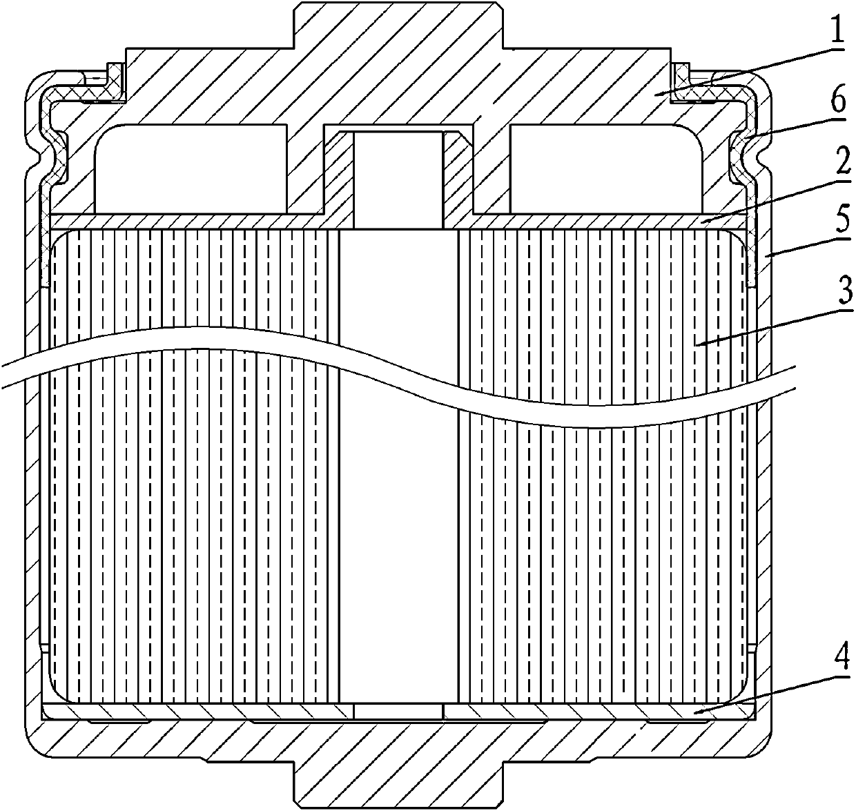
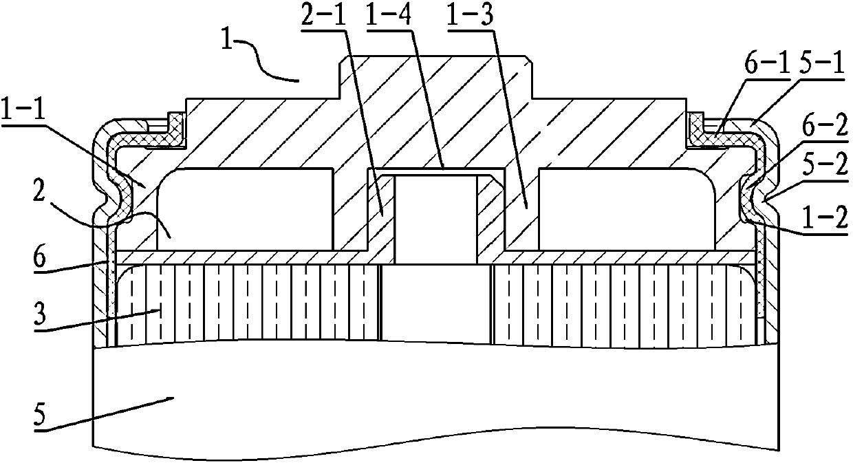

Image

  • Electric energy storing device
  • Electric energy storing device
  • Electric energy storing device

Examples


Embodiment Construction

[0029] Embodiment 1 of the electric energy storage device of the present invention, such as figure 2 and image 3 As shown, the electric energy storage device includes an end cover 1, an upper current collecting plate 2, a columnar cell 3, a lower current collecting plate 4, a housing 5, and an insulating sealing sleeve 6, and the upper end of the electric energy storage device has a terminal The electrode lead-out structure formed by the cover 1 and the upper current collecting plate 2 and the insulating sealing structure formed by the electrode lead-out structure, the insulating sealing sleeve 6 and the housing 5 . The upper current collecting plate 2 is welded on the upper end surface of the electric core 3, and is in electrical contact with the electric core 3, and the end cover 1 is conductively fixed on the upper end surface of the current collecting plate, and the end cover is composed of an end cover plate body, an end cover plate The lower end surface of the body is...


PUM


Abstract

The invention discloses an electric energy storing device, wherein an insulating seal body of the electric energy storing device is an insulating seal cover covered on the periphery of an electrode leading-out structure, one end of the insulating seal cover is erected on the end face of the electrode leading-out structure, which is back to an electric core, the other end of the insulating seal cover is covered on the periphery of the electric core, and a positioning drape which is complementarily fit with a deformed drape and embedded into a groove is arranged on the periphery in the middle of the insulating seal cover. Therefore, the electrode leading-out structure and a housing can be separated from each other by the integrated insulating seal cover, the insulating seal cover can be conveniently and quickly sleeved on the periphery of the electrode leading-out structure, and the insulating seal cover can be tightly compressed on the electrode leading-out structure by a sealed flange and the deformed drape on the housing, so that the assembly technology can be simplified, the assembly period can be shortened, the assembly efficiency can be improved, the loss of the material in the electric energy storing device can be reduced, and the manufacture cost can be reduced.

Description

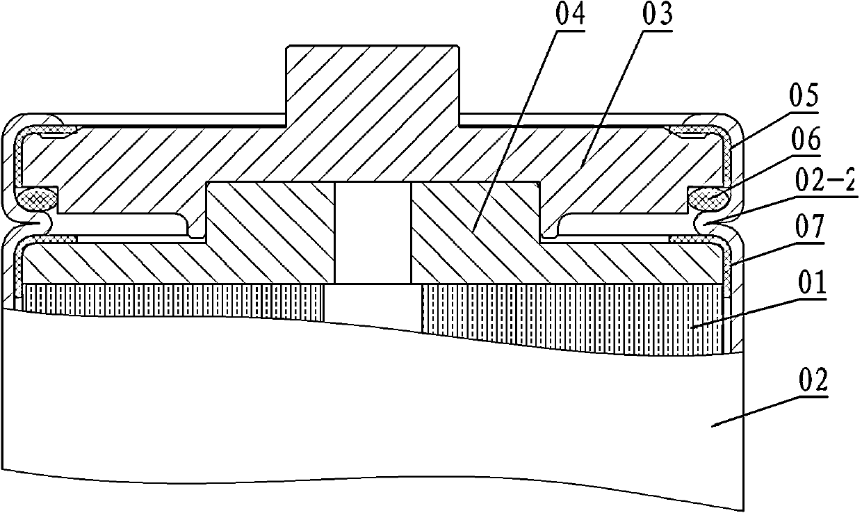
technical field [0001] The invention relates to the technical field of electric energy storage devices. Background technique [0002] At present, the commonly used electrical energy storage devices (including batteries and supercapacitors) have electrode lead insulation and sealing structures such as figure 1 As shown, the electric energy storage device is composed of a cell 01, a casing 02, an electrode lead-out structure and an insulating sealing body. The casing 02 is electrically connected to the lower end of the cell 01, and the electrode lead-out structure is conductively connected to the upper end of the cell 01. , so it is necessary to interpose an insulating sealing body between the electrode lead-out structure and the casing to avoid the short-circuit problem caused by the contact between the electrode lead-out structure and the casing 02 . In the specific structure, the shell 02 is processed with deformed folds 02-1 that sink into the gap between the end cover 03...

Claims


Application Information

Patent Timeline
Patent Type & Authority Applications(China)
IPC IPC(8): H01M2/34H01M2/08H01G11/52H01G11/80
CPCY02E60/10
Inventor 袁召聂丹丹李欢徐梅董济锐梁晓鸽
Owner ZHENGZHOU SINO CRYSTAL DIAMOND
Learn More