
Retro-reflection based arterial highway non-control intersection night-driving safety facility design method

A driving safety and design method technology, applied to roads, roads, road signs, etc., can solve the problems of no clear regulations on vehicle speed control at intersections, lack of supervision and management of main control of laws and regulations, and insufficient research on psychological control, so as to increase the three-dimensional sense and Sense of distance, ensuring rhythm and regularity, and strengthening night vision

Inactive Publication Date: 2013-07-31
WUHAN UNIV OF TECH
View PDF6 Cites 9 Cited by
  • Summary
  • Abstract
  • Description
  • Claims
  • Application Information

AI Technical Summary

Problems solved by technology

At uncontrolled highway intersections, the main control of laws and regulations lacks effective supervision and management; psychological control is insufficiently studied in the field of optical illusion applications; relevant engineering control regulations have no clear regulations for uncontrolled intersections on arterial highways
The "Specifications for the Setting of Highway Traffic Signs and Markings: JTGD82-2009" promulgated in 2009 stipulates the setting conditions, setting positions and setting specifications of deceleration markings, but there is no clear regulation on the speed control of intersections

Method used


Image

  • Retro-reflection based arterial highway non-control intersection night-driving safety facility design method
  • Retro-reflection based arterial highway non-control intersection night-driving safety facility design method
  • Retro-reflection based arterial highway non-control intersection night-driving safety facility design method

Examples


Embodiment Construction

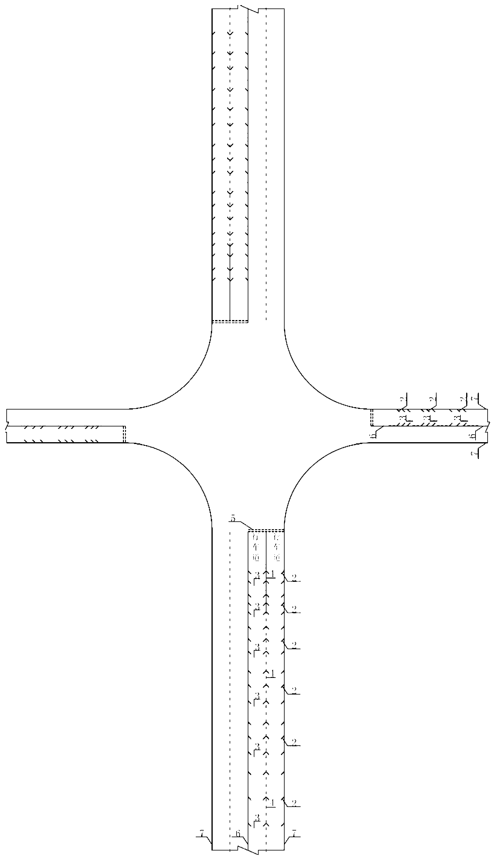
[0037] 1) When the vehicle decelerates to the target speed of 20km / h, if the driver observes that there is a vehicle on the intersecting road, the driver needs to continue to decelerate to stop and give way. Therefore, a 10-20m interval is reserved in front of the highway intersection to start setting the road surface lateral vibration deceleration markings 3 .

[0038] 2) According to the highway traffic signs and markings setting specifications, set the road surface lateral vibration deceleration markings, using -3m / s 2 Acceleration, each group of 2 to 3, each 0.3m width, the vibration time interval is roughly equal.

[0039] 3) Clean the road surface and the edge of the lane 100m before the intersection, and set up the first set of lateral vibration deceleration markings on the road surface from 10 to 20m before the intersection. The length of lateral vibration deceleration markings on the road surface of the main road is 75-80m, and there are 7 groups in total. The spaci...


PUM


Abstract

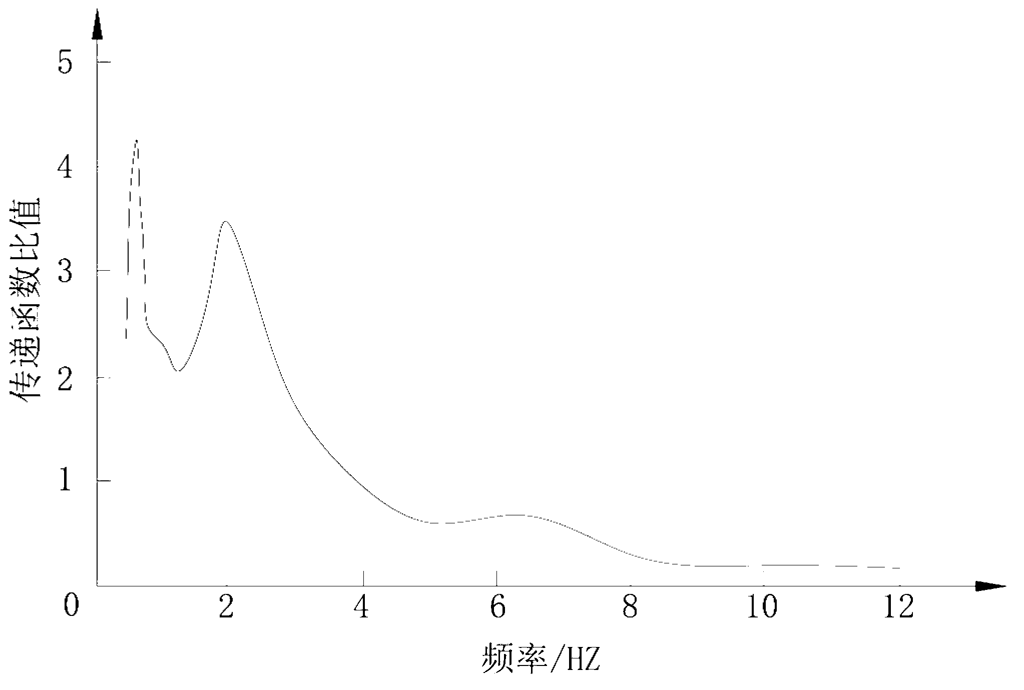
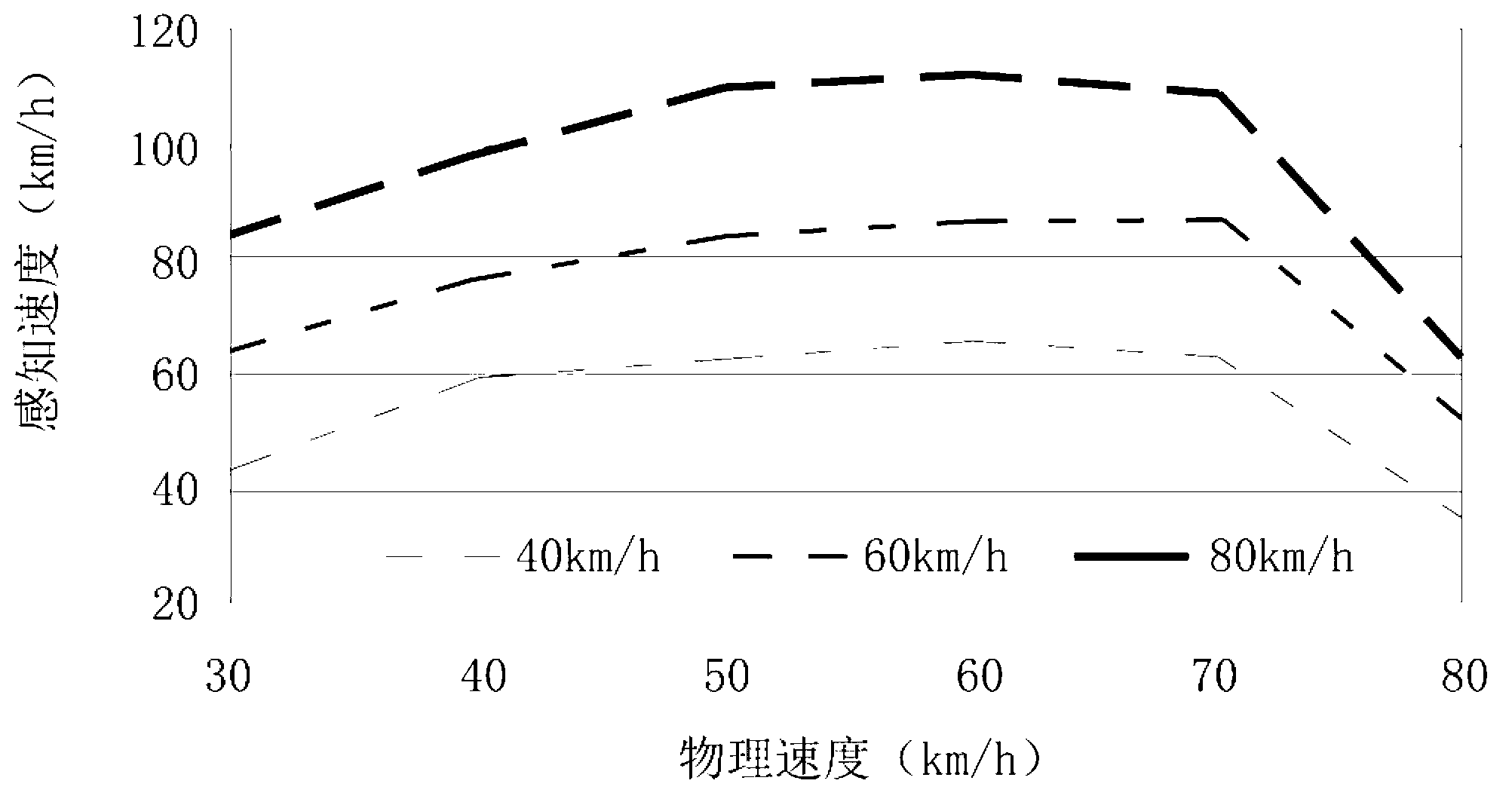
The invention relates to a retro-reflection based arterial highway non-control intersection night-driving safety facility design method. Based on drivers' vibration perception and visual perception principle and by comprehensive application of involuntary speed reduction and voluntary speed reduction methods, in an intersection functional zone, seven road-surface lateral oscillation deceleration markings of 80-100m length at the vibrational frequency of 1-2 HZ are arranged such that a driver has a vibration discomfortableness so as to passively decelerate; frequency-conversion comb-teeth-shaped visual illusion deceleration markings of about 50m length at the median frequency of 4-8 HZ are arranged at the edge of a lane such that a speed that a driver senses is faster than an actual speed so as to actively decelerate; in an intersection physical zone, five intersection contour warning marks which are arranged 12-20m away from each other are disposed along the edge of a turning curve; and a retro-reflection material is used to design the deceleration markings and the warning marks such that night legibility and warning effect at intersections are raised. The design provided by the invention is suitable for arterial highway non-control intersections with the night travel-speed of 40-80km / h.

Description

technical field [0001] The invention relates to the design of safety facilities for driving at night at uncontrolled intersections on arterial highways based on retroreflection. The design is used to enhance the driver's ability to recognize the intersection at night, and at the same time, the vehicle speed active control and passive control technology are used to control the vehicle entering the intersection. Combined way to improve night driving safety at highway intersections. Background technique [0002] Many rural arterial road intersections in my country have backward traffic management, low or no lighting at night, insufficient traffic safety facilities, and traffic accidents often occur due to speeding or failure to give way according to regulations. On the one hand, there is little traffic at night at uncontrolled intersections on arterial highways, traffic supervision is weak, and driving violations occur frequently; Some safety signs and markings are invalid. A...

Claims


Application Information

Patent Timeline
IPC IPC(8): E01C1/02E01F9/04E01F9/047E01F9/053E01F9/08E01F9/50E01F9/524E01F9/535E01F9/576
Inventor 徐良杰余金林杜志刚金小莹冯超刘启远秦亚晓
Owner WUHAN UNIV OF TECH
Learn More