Topology discovery method and topology discovery system

A technology of topology discovery and topology entry, applied in the field of network communication

Active Publication Date: 2013-07-31
武汉神州数码云科网络技术有限公司
View PDF4 Cites 8 Cited by
  • Summary
  • Abstract
  • Description
  • Claims
  • Application Information

AI Technical Summary

Problems solved by technology

[0005] In view of this, the present invention proposes a topology discovery method and system to solve the technical p

Method used


Image

  • Topology discovery method and topology discovery system
  • Topology discovery method and topology discovery system
  • Topology discovery method and topology discovery system

Examples


Embodiment 1

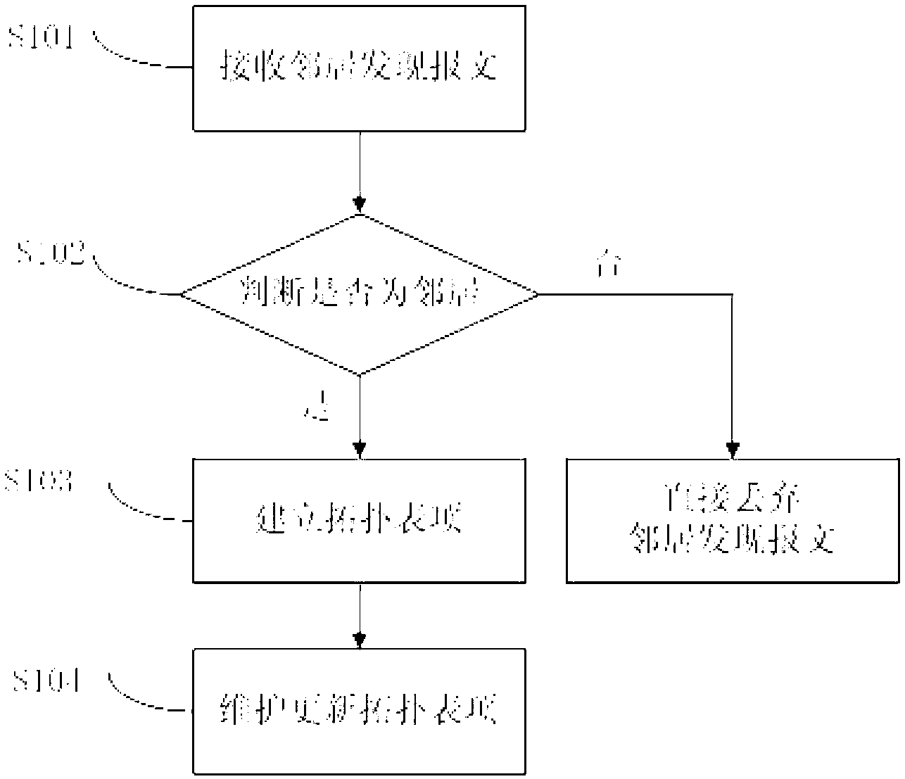
[0065] See attached figure 1 , Embodiment 1 of the present invention discloses a topology discovery method, including:

[0066]Step S101, the receiving device receives the neighbor discovery message sent by the sending device;

[0067] Step S102, the receiving device judges whether the sending device is a neighbor according to the first neighbor entry of the receiving device;

[0068] Step S103, if yes, the receiving device and the sending device receive the topology entry establishment message, establish a connection (Line) according to the first neighbor entry and the second neighbor entry of the sending device, and pass the connection to the first neighbor table item and the neighbor device other than the receiving device and the sending device in the second neighbor table entry, and establishes a topology table entry;

[0069] Step S104, the receiving device maintains and updates topology entries.

[0070] In step S102 of Embodiment 1 of the present invention, according...

Embodiment 2

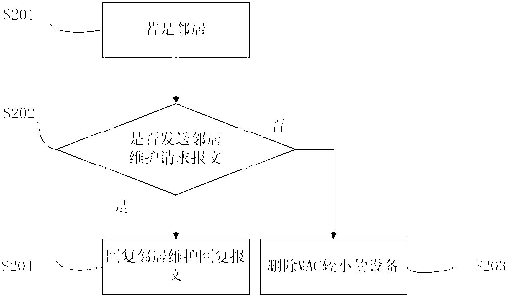
[0143] The first embodiment of the present invention discloses a topology discovery method, and the second embodiment of the present invention discloses a topology discovery method. On the basis of the topology discovery method disclosed in the first embodiment of the present invention, the method further includes:

[0144] Step S201, if the receiving device and the sending device are neighbors;

[0145] Step S202, in a preset time period, according to whether the device with a smaller MAC among the receiving device and the transmitting device sends a neighbor maintenance request message, determine the neighbor state;

[0146] Step S203, if not, delete the device with smaller MAC;

[0147] Step S204, if yes, the device with the larger MAC in the receiving device and the transmitting device replies to the neighbor maintenance reply message to maintain the neighbor relationship.

[0148] Similarly, the neighbor maintenance request message is carried by the Layer 2 multicast mes...

Embodiment 3

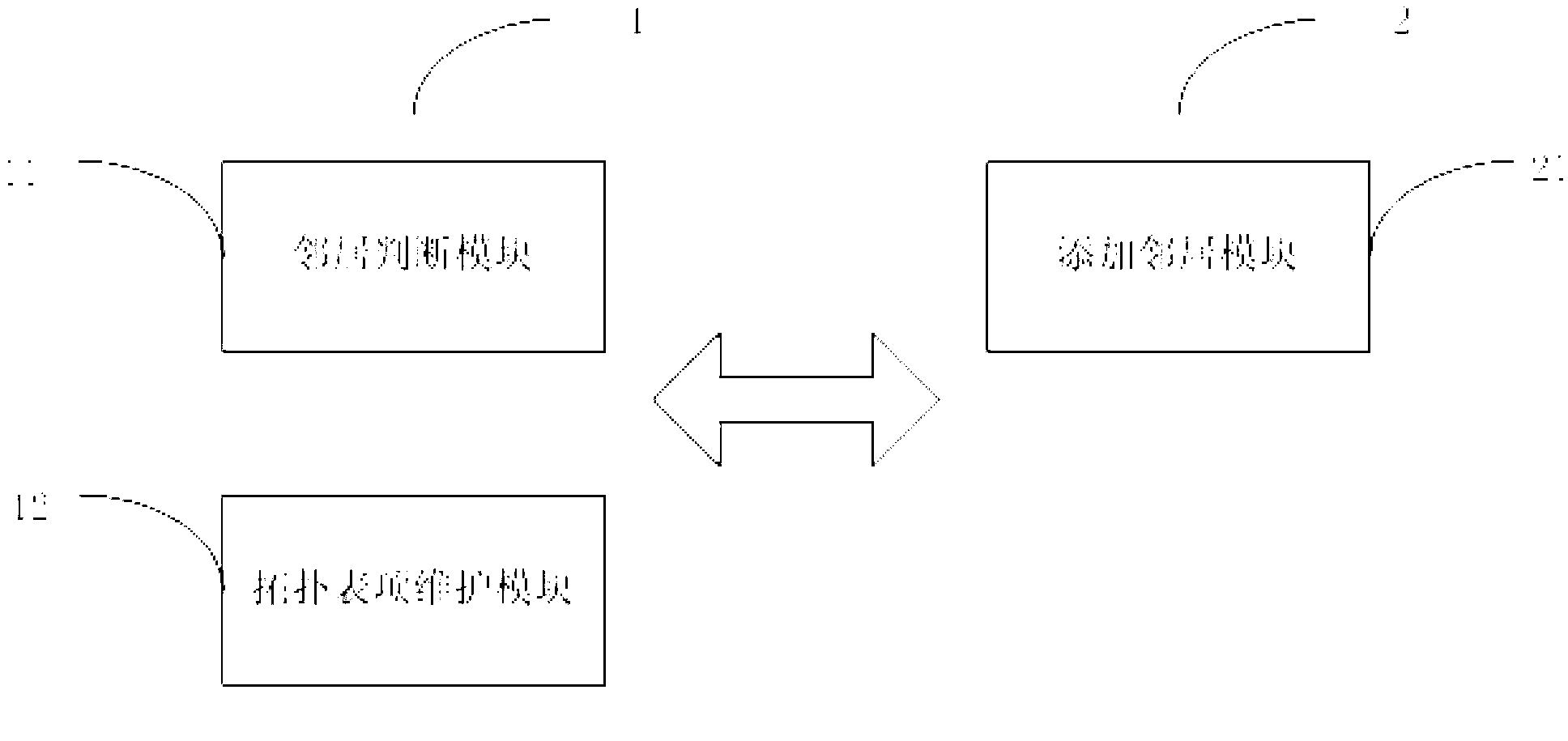
[0171] Embodiment 1 of the present invention discloses a topology discovery method. Correspondingly, Embodiment 3 of the present invention discloses a topology discovery device, such as image 3 shown.

[0172] A topology discovery device, comprising a receiving device 1 for receiving a neighbor discovery message, and judging whether the sending device 2 is a neighbor according to a first neighbor entry of the receiving device;

[0173] If so, receive the topology entry establishment message, establish a connection according to the first neighbor entry and the second neighbor entry of the sending device 2, and transfer the connection to the neighbor devices other than the sending device in the first neighbor entry, Create topology entries, maintain and update topology entries;

[0174] Sending device 2, used to send neighbor discovery packets;

[0175] Receive the topology entry establishment message, establish a connection according to the second neighbor entry and the firs...


PUM


Abstract

The invention discloses a topology discovery method which comprises the steps that receiving equipment receives a neighbor discovery message transmitted by transmitting equipment; the receiving equipment judges whether the transmitting equipment is a neighbor according to a first neighbor table entry of the receiving equipment; if so, the receiving equipment and the transmitting equipment receive a topology table entry establishing message; a connecting line is established according to the first neighbor table entry and a second neighbor table entry of the transmitting equipment, and transferred to neighbor equipment in the first neighbor table entry and the second neighbor table entry, except for the receiving equipment and the transmitting equipment; a topology table entry is established; and the receiving equipment maintains and updates the topology table entry. The invention further discloses a topology discovery system. According to the topology discovery method and the topology discovery system, link statuses in an entire network can be discovered independent of an upper layer protocol, and the link statuses of other equipment can be viewed on any equipment in the network.

Description

technical field [0001] The present invention relates to the technical field of network communication, in particular to a topology discovery method and system. Background technique [0002] With the development of network technology, the scale of the network continues to expand, and the complexity of the network increases day by day, which prompts users to have higher and higher requirements for network management. [0003] Network redundancy has become a key feature of today's networks. For example, a redundant backup server means that two servers back up each other. When one server fails, the other server immediately replaces the failed server. However, in the process of redundant backup, when the primary server and the backup server lose contact, the link status cannot be determined. [0004] In the prior art, the link state in the network can be determined by using the link layer topology discovery, but it needs to be realized by using the upper layer protocol, such as ...

Claims


Application Information

Patent Timeline
IPC IPC(8): H04L12/24H04L12/751H04L45/02
Inventor 付增福
Owner 武汉神州数码云科网络技术有限公司
Why Eureka
Try Eureka