Louvered Vertical Axis Resistance Wind Turbine

A louver-type, vertical-axis technology, applied to wind turbines, wind turbines at right angles to the wind direction, control of wind turbines, etc., can solve problems such as no self-starting settings, no deceleration or shutdown control settings, and the improvement of efficiency

Active Publication Date: 2015-09-30
魏宏君
View PDF5 Cites 0 Cited by
  • Summary
  • Abstract
  • Description
  • Claims
  • Application Information

AI Technical Summary

Problems solved by technology

[0006] (1) The non-retractable right-angle impeller casing on the upper part of "a wind collection device for vertical axis wind power generation" has a large wind blocking area, which affects the improvement of its efficiency;
[0007] (2) The rotating shaft of the movable blade of "a wind collecting device for vertical axis wind power generation" is on the edge of the blade, which is next to the fixed blade below when it is in the horizontal position, so it is easy to move the movable blade in the weather of wind, snow or sand. Snow or sand deposited between the fixed blades will cause the wind turbine not to work normally or accelerate the damage of the wind turbine;
[0008] (3) "A wind collection device for vertical axis wind power generation" has no self-starting setting;
[0009] (4) "A wind collection device for vertical axis wind power generation" has no deceleration or shutdown control settings

Method used


Image

  • Louvered Vertical Axis Resistance Wind Turbine
  • Louvered Vertical Axis Resistance Wind Turbine
  • Louvered Vertical Axis Resistance Wind Turbine

Examples


Embodiment Construction

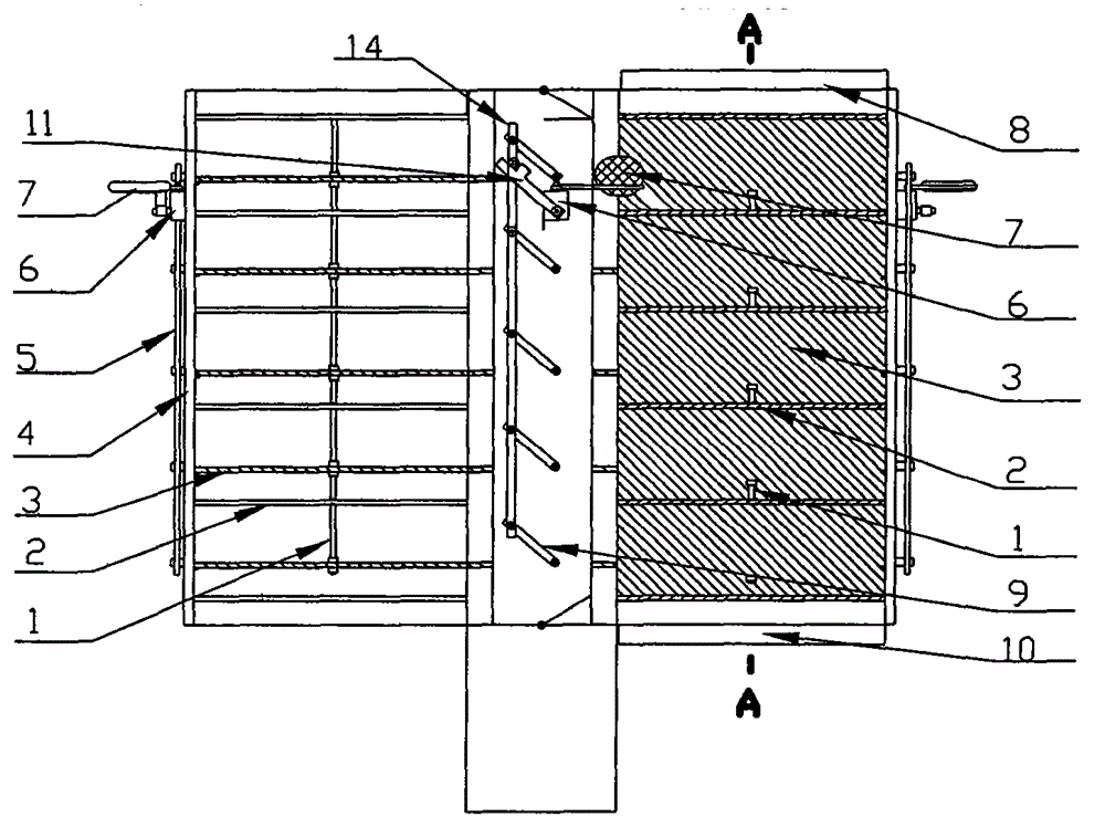
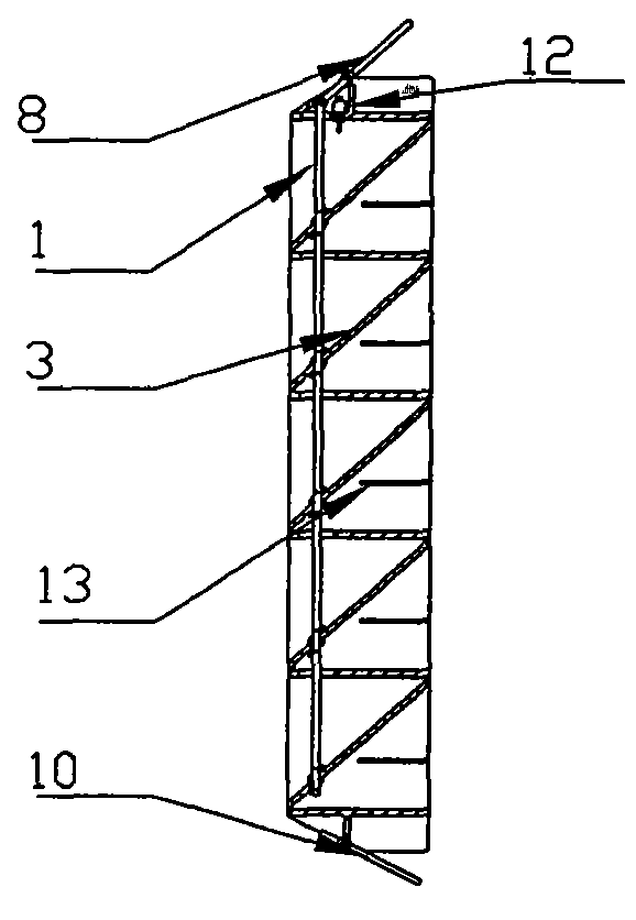
[0028] see figure 1 , figure 2 and image 3 , when a stationary wind turbine encounters a certain strength of wind, there is always a fan blade frame (4) at the position with the largest windward area, and its top moving plate (8) and bottom moving plate (10) are blown, while the top moving plate (8) Drive the moving plate (3) upward through the self-starting rod (1), and the moving plate (3) contacts with the upper and lower fixed plates (2) to form the largest wind resistance area. The fan blade frame (4) receives the thrust of the wind, The wind turbine realizes self-starting.

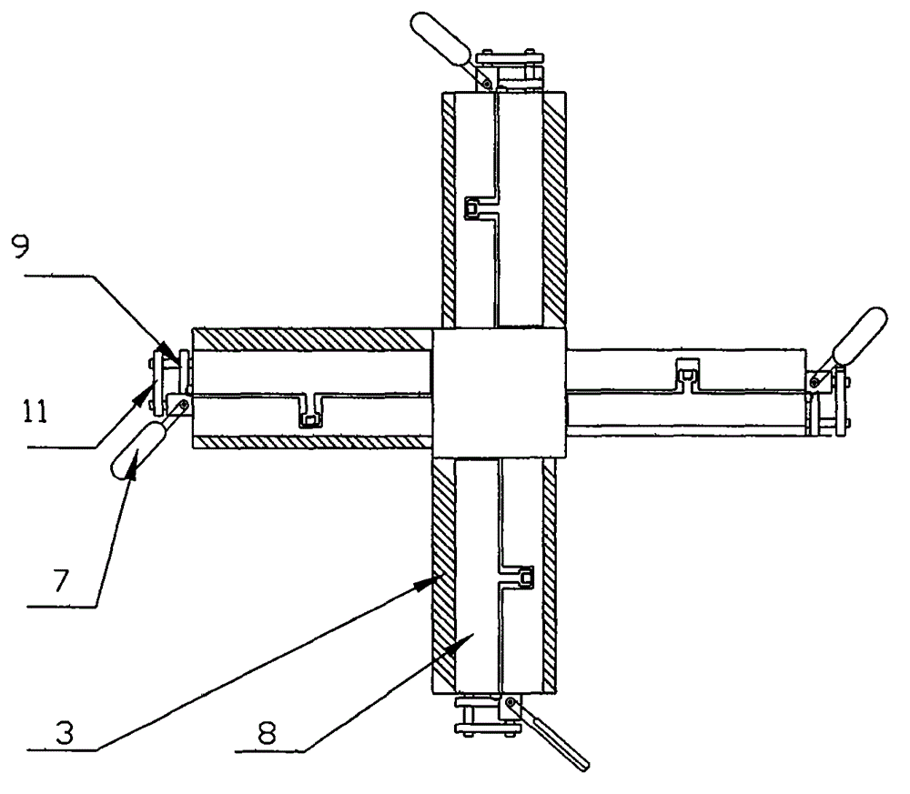
[0029] see Figure 5 , Figure 6 , Figure 7 and Figure 8 , when a fan blade frame (4) rotates to a specific position during the rotation process, the first moving blade (7) installed on the outside of the frame is first erected by the wind, resulting in a larger wind resistance area, so it is blown to rotate for a certain Angle, the rotational torque generated by it becomes the vertical ro...


PUM


Abstract

The invention discloses a louvered vertical axis resistance wind turbine, and belongs to the field of wind power generation. The principle includes that four louvered fan blades are symmetrically mounted on a vertical axis, each fan blade comprises a plurality of movable plates and fixed plates which are mounted into a vertical row at intervals, one fan blade is constantly placed at a windward position when the fixed wind turbine encounters wind with a certain strength, the movable plates at the top of the fan blade are blown and driven to realize self-starting, first-moving blades mounted on the outer side surfaces of the fan blades shift the movable plates through helical gear boxes at proper positions in the rotating process to generate rotating torque, the movable plates drop to a position parallel to the fixed plates when the first-moving blades do not generate the rotating torque, so that rotating resistance is minimum, the rotating torque of a resistance fan is in direct proportion to a windward area, the rotating resistance is in direct proportion to a choke area, the windward area to the choke area can reach hundreds to one by the aid of a movable plate structure, and the efficiency of the resistance wind turbine is greatly improved. By the aid of the structure, the manufacturing cost of the resistance wind turbine is low, and power can be improved by increasing the areas, so that wind power generation is high-power and low-cost.

Description

a technical field [0001] The invention belongs to a vertical axis resistance type wind power generator in the field of wind power generation. Two background technology [0002] 1 Typical resistance wind turbine [0003] Typical resistance wind turbines generate torque because the two sides of the blades have different drag coefficients, and the ratio is about 1 / 2 at rest, and the areas of the blades at the windward and resistance positions are constant. This makes typical drag wind turbines produce very little speed and torque and are very inefficient. [0004] 2 A wind collection device for vertical axis wind power generation (Patent No. ZL201220026570.4) [0005] "A wind collection device for vertical axis wind power generation" has the following disadvantages: [0006] (1) The non-retractable right-angle impeller casing on the upper part of "a wind collection device for vertical axis wind power generation" has a large wind blocking area, which affects the improvement o...

Claims


Application Information

Patent Timeline
Patent Type & Authority Patents(China)
IPC IPC(8): F03D3/06F03D7/06
CPCY02E10/74Y02P70/50
Inventor 魏宏君
Owner 魏宏君
Why Eureka
Try Eureka