Elevator control system

An elevator control and control device technology, applied in elevators, transportation and packaging, etc., can solve problems such as the inability to effectively exert the driving ability of the traction machine, the detection error of the maximum speed and acceleration, and the decline of elevator operation efficiency.

Active Publication Date: 2012-11-28
MITSUBISHI ELECTRIC CORP
View PDF1 Cites 0 Cited by
  • Summary
  • Abstract
  • Description
  • Claims
  • Application Information

AI Technical Summary

Problems solved by technology

[0004] However, the maximum speed and acceleration of the speed mode are set to be low in consideration of, for example, the detection error of the load in the car.
Therefore, when the elevator is operated in the speed mode set in this way, the car is moved with a margin in the drive capacity of the traction machine, and the drive capacity of the traction machine cannot be efficiently utilized.
As a result, the operating efficiency of the elevator is reduced

Method used


Image

  • Elevator control system
  • Elevator control system
  • Elevator control system

Examples


Embodiment approach 1

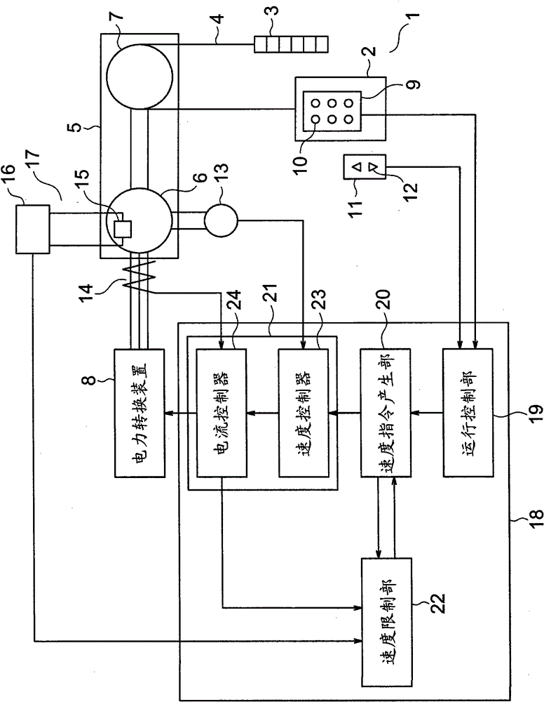
[0014] figure 1 It is a configuration diagram showing an elevator according to Embodiment 1 of the present invention. In the figure, in a hoistway 1 , a car 2 and a counterweight 3 are suspended by main ropes 4 . A traction machine (drive device) 5 for moving the car 2 and the counterweight 3 is provided on the upper portion of the hoistway 1 . The traction machine 5 has a motor 6 and a drive pulley 7 rotated by the motor 6 .

[0015] The motor 6 is a permanent magnet motor. The driving pulley 7 is rotated by power supply to the motor 6 . The electric motor 6 is powered by the power conversion device 8 . In addition, the main rope 4 is wound around the drive pulley 7 . The car 2 and the counterweight 3 move in the hoistway 1 by the rotation of the drive pulley 7 .

[0016] A car operating panel 9 is provided in the car 2 . A plurality of car call buttons 10 for performing call registration are provided on the car operating panel 9 . Moreover, the hall operation panel 1...


PUM


Abstract

In an elevator control system, the feed to a motor of a driving device for moving a cage is controlled by a controller. When the temperature of any predetermined apparatus targeted for control including the driving device reaches a predetermined temperature reference value, a temperature alarm signal is output from a temperature signal generator to the controller. When there is no reception of the temperature alarm signal, the controller performs a speed priority control with the maximum value of the rotating speed of the motor set as a predetermined speed by causing a weak field current to flow in the motor. On the other hand, when the controller is receiving the temperature alarm signal, it performs a torque priority control to lower the maximum value of the rotating speed of the motor than the predetermined speed within such a range that the output torque may be maximum with respect to the feed to the motor, by reducing the weak field current to the motor to a lower level than in the speed priority control.

Description

technical field [0001] This invention relates to elevator control systems for controlling movement of cars. Background technique [0002] Conventionally, an elevator control device has been proposed that predicts and calculates the continuous temperature state of structural equipment in order not to overload predetermined structural equipment of the elevator, and controls the operation of the elevator based on the predicted temperature state. In this conventional elevator, by switching between high-speed and low-speed speed modes, the elevator is operated within a range that does not exceed the temperature limit of structural equipment (see Patent Document 1). [0003] Patent Document 1: WO2004 / 030627 [0004] However, the maximum speed and acceleration of the speed mode are set to be low in consideration of, for example, a detection error of the load in the car. Therefore, when the elevator is operated in such a set low speed mode, the car is moved with a margin in the dr...

Claims


Application Information

Patent Timeline
Patent Type & Authority Patents(China)
IPC IPC(8): B66B5/02
CPCB66B1/30B66B5/02
Inventor 柴田益诚
Owner MITSUBISHI ELECTRIC CORP
Why Eureka
Try Eureka