Pedaled hydraulic driving power-assisting clutch device

A clutch device and liquid drive technology, applied in the direction of clutches, mechanical equipment, etc., can solve the problems that it is difficult to meet the drilling needs of large-scale drilling rigs, it is difficult to meet the needs of new models, and the pneumatic separation speed is fast, so as to improve drilling Performance, micro-motion soft control effect, and thorough separation effect

Active Publication Date: 2013-08-07
H H DRILL TECH DRILLING MACHINERY CO LTD
View PDF3 Cites 2 Cited by
  • Summary
  • Abstract
  • Description
  • Claims
  • Application Information

AI Technical Summary

Problems solved by technology

At present, deep hole core drilling rigs, such as XY-6, XY-8, and XY-9 drilling rigs, have increased power and system torque transmission, and the clutch separation device still uses the manual lever structure of the original small machine, which is difficult to meet Drilling needs for larger rigs
[0003] If the original manual lever type clutch separation structure is used in a larger model, there are some problems: 1. Due to the increase in the type of drilling rig, the axial force required for clutch separation will increase greatly, and the manual lever type separation mechanism , it is obviously difficult to simply increase the power arm or change the power arm to achieve the ideal separation effect, and at the same time, to meet the comfort of the operation, it is difficult to meet the needs of the new model
2. The original manual lever type separation mechanism has its own defects
For the clutch and separation device of the XY-5 drilling rig, we have also tried the pneumatic clutch and separation structure commonly used in oil drilling rigs, but the effect is not good because the pneumatic separation speed is too fast

Method used


Image

  • Pedaled hydraulic driving power-assisting clutch device

Examples


Embodiment Construction

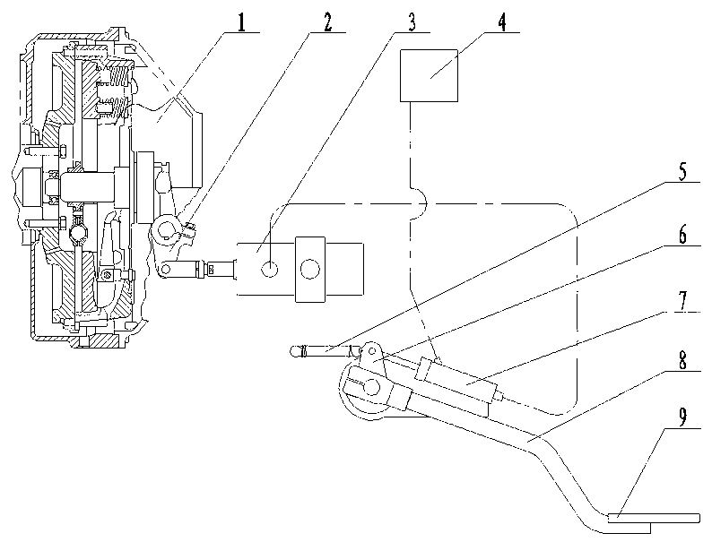
[0012] A foot hydraulic power-assisted clutch device, including a normally closed clutch 1 and a clutch operating mechanism, the normally closed clutch 1 is provided with a compression sleeve and a drive handle 2, and the drive handle 2 is connected to the compression sleeve through a fork assembly , the clutch operating mechanism includes a piston automatic reset cylinder 3 and a thrust pressurization cylinder 7, the bore of the piston automatic reset cylinder 3 is larger than that of the thrust pressurization cylinder 7, and the rear chamber of the piston automatic reset cylinder 3 is set as high-pressure closed Cavity, the front chamber of the piston automatic reset cylinder 3 is set as a booster chamber, the piston rod of the piston automatic reset cylinder passes through the booster chamber and is hinged with one end of the drive handle 2, and the thrust pressurization cylinder 7 is provided with a pressurization chamber, and the thrust The pressurized chamber of the press...


PUM


Abstract

A pedaled hydraulic driving power-assisting clutch device comprises a normally closed clutch and a clutch operating mechanism. The normally closed clutch is provided with a compression sliding sleeve and a driving handle, the driving handle is connected with the compression sliding sleeve through a shifting fork component, the clutch operating mechanism comprises an automatic piston reset cylinder and a thrust pressurizing cylinder, a rear cavity of the automatic piston reset cylinder is a high-pressure closed cavity, a front cavity of the automatic piston reset cylinder is a reinforcement cavity, a piston rod of the automatic piston reset cylinder penetrates through the reinforcement cavity and is hinged to one end of the driving handle, the thrust pressurizing cylinder is provided with a pressurizing cavity, the pressurizing cavity of the thrust pressurizing cylinder is communicated with the reinforcement cavity of the automatic piston reset cylinder through an oil pipe, and a swing arm is hinged to the end of a piston rod of the thrust pressurizing cylinder. The pedaled hydraulic driving power-assisting clutch device is comfortable to operate, drilling construction of a drilling machine can be slightly, softly and stably controlled, the drilling capacity and the drilling performance of the drilling machine are obviously improved, and the capacity of exploration technology equipment is greatly enhanced.

Description

technical field [0001] The invention relates to engineering geological exploration equipment, in particular to a foot-operated liquid-driven power-assisted clutch device. Background technique [0002] Since 2006, the State Council promulgated the "Decision on Strengthening Geological Work". my country's mining industry has recovered rapidly, geological core drilling has grown rapidly, and investment in mineral exploration has continued to increase accordingly. Geological exploration equipment, vertical shaft core drilling rigs are still the absolute main force in the exploration market. XY-4, XY-42, XY-44, and XY-5 drilling rigs basically cover shallow and middle layer exploration. Deep exploration and ore prospecting work has also entered a stage of rapid development. It can be said that the new round of geological and mineral exploration work in my country mainly focuses on deep exploration and blind exploration. Geological prospecting has shifted from shallow and mid-d...

Claims


Application Information

Patent Timeline
Patent Type & Authority Applications(China)
IPC IPC(8): F16D48/04
Inventor 马增福
Owner H H DRILL TECH DRILLING MACHINERY CO LTD
Why Eureka
Try Eureka