
Motorcycle clutch release travel adjusting mechanism

A separation stroke and adjustment mechanism technology, which is applied in the direction of friction clutch, clutch, mechanical drive clutch, etc., can solve the problems of inconsistent displacement, large tolerance, increased parts processing technology and manufacturing difficulty, so as to improve reliability and ensure separation stroke , the effect of eliminating size differences

Inactive Publication Date: 2011-12-14
CHONGQING JIANSHE MOTORCYCLE CO LTD
View PDF3 Cites 0 Cited by
  • Summary
  • Abstract
  • Description
  • Claims
  • Application Information

AI Technical Summary

Problems solved by technology

That is, the cable can only move about 15mm. In order to ensure that the separation stroke of the clutch is within the design range, it is necessary to strictly control the parts of the engine clutch control mechanism to ensure that the processing size of each part is basically the same, which increases the number of parts. Processing technology and manufacturing difficulty (due to the processing tolerance of the parts, the process can only control the tolerance within a certain range, and cannot completely eliminate the processing tolerance), and the motorcycle clutch control mechanism is relatively complicated. There are many components between the ejector rods at the clutch, so the cumulative tolerance is relatively large, and the design of the clutch separation stroke is relatively demanding
In this way, if the accumulated tolerance cannot be eliminated, the initial installation position of the operating arm of the mechanism cannot be determined, and the displacement of the push rod is inconsistent under the same rotation angle of the operating arm, resulting in incomplete separation of the clutch

Method used


Image

  • Motorcycle clutch release travel adjusting mechanism
  • Motorcycle clutch release travel adjusting mechanism

Examples


Embodiment Construction

[0016] The structure of the present invention will be further described in detail below in conjunction with the accompanying drawings and specific embodiments.

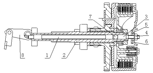
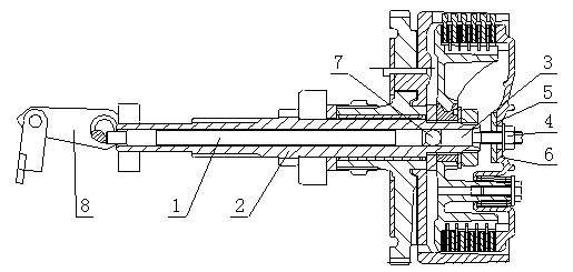
[0017] Such as figure 1 As shown, a motorcycle clutch separation stroke adjustment mechanism includes a push rod 1, and the push rod 1 is slidably arranged in the push rod installation sleeve 2, and also includes an adjusting screw 3, a locking nut 4, and an adjusting nut 5. One end of the adjusting screw 3 is slidably located in the mandrel mounting sleeve 2 and is offset against the mandrel 1, and the other end of the adjusting screw 3 is provided with a through hole on the pressure plate 6 facing the adjusting screw 3, and the through hole is fixed. The adjustment nut 5 is described, the end of the adjustment screw 3 away from the push rod 1 is screwed into the adjustment nut 5 and the lock nut 4 is screwed after passing through the through hole, and the lock nut 4 faces the side of the pressure plate 6 The surfac...


PUM


Abstract

The invention discloses a motorcycle clutch release travel adjusting mechanism which comprises a push rod, wherein the push rod can be slidably arranged in a push rod installing sleeve. The release travel adjusting mechanism provided by the invention is characterized by comprising an adjusting screw, a locking nut and an adjusting nut, wherein one end of the adjusting screw can be slidably positioned in the push rod installing sleeve and props against the push rod; a platen opposite to the other end of the adjusting screw is provided with a through hole through which the adjusting screw can pass, and the through hole is fixedly provided with a adjusting nut; and one end, far from the push rod, of the adjusting screw is screwed in the adjusting nut and passes through the through hole so as to be connected with the locking nut in a screwing manner, and the surface area of one side, facing to the platen, of the locking nut is greater than the area of the through hole. Compared with the prior art, the clutch release travel adjusting mechanism provided by the invention can be used for well eliminating the dimensional discrepancy caused by the allowance, controlling the release travel of the clutch, ensuring the release travel in the rang of design and ensuring the release travel of the clutch, thereby improving the separating and combining reliability of the clutch.

Description

technical field [0001] The invention relates to a motorcycle clutch, in particular to a motorcycle clutch separation stroke adjustment mechanism. [0002] Background technique [0003] The clutch part of the motorcycle engine is an important part of the engine power output and cut-off. It provides the normal functions of shifting, starting, driving and parking of the motorcycle; when the motorcycle is shifting, the clutch is used to cut off the power output and shift into the predetermined gear. Then let the clutch combine, the power of the engine passes through transmission components such as the clutch and transmission gear, and finally outputs to the wheels to allow the motorcycle to run. Existing motorcycle clutches generally include a driven hub, a pressure plate, and a friction transmission assembly between the two. The friction transmission assembly includes clutch plates, friction plates, etc.; One end of the force-applying member on the upper part can slide throug...

Claims


Application Information

Patent Timeline
IPC IPC(8): F16D13/75
Inventor 向晓明
Owner CHONGQING JIANSHE MOTORCYCLE CO LTD
Learn More