Fast assembly and disassembly mechanism for nonlinear large-aperture optical elements
A technology of optical components and disassembly mechanism, applied in the direction of optical components, optics, installation, etc., can solve the problems of low efficiency and long time consumption, reduce positioning time, low manufacturing cost, improve online disassembly and installation and fixation efficiency effect
- Summary
- Abstract
- Description
- Claims
- Application Information
AI Technical Summary
Problems solved by technology
Method used
Image
Examples
specific Embodiment approach 1
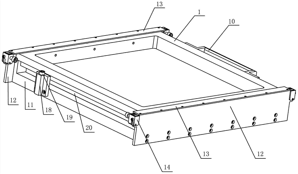
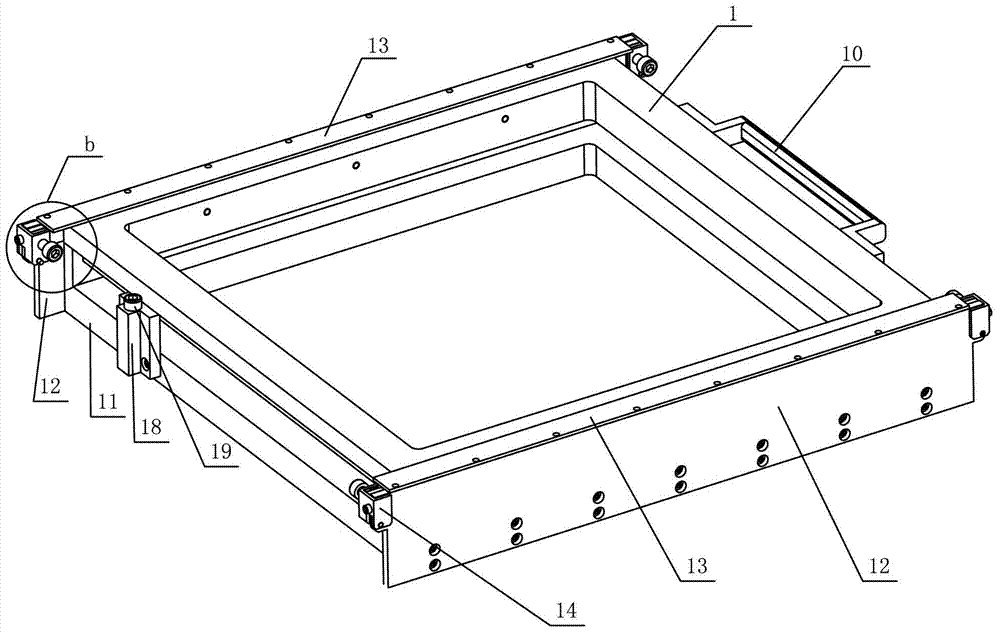
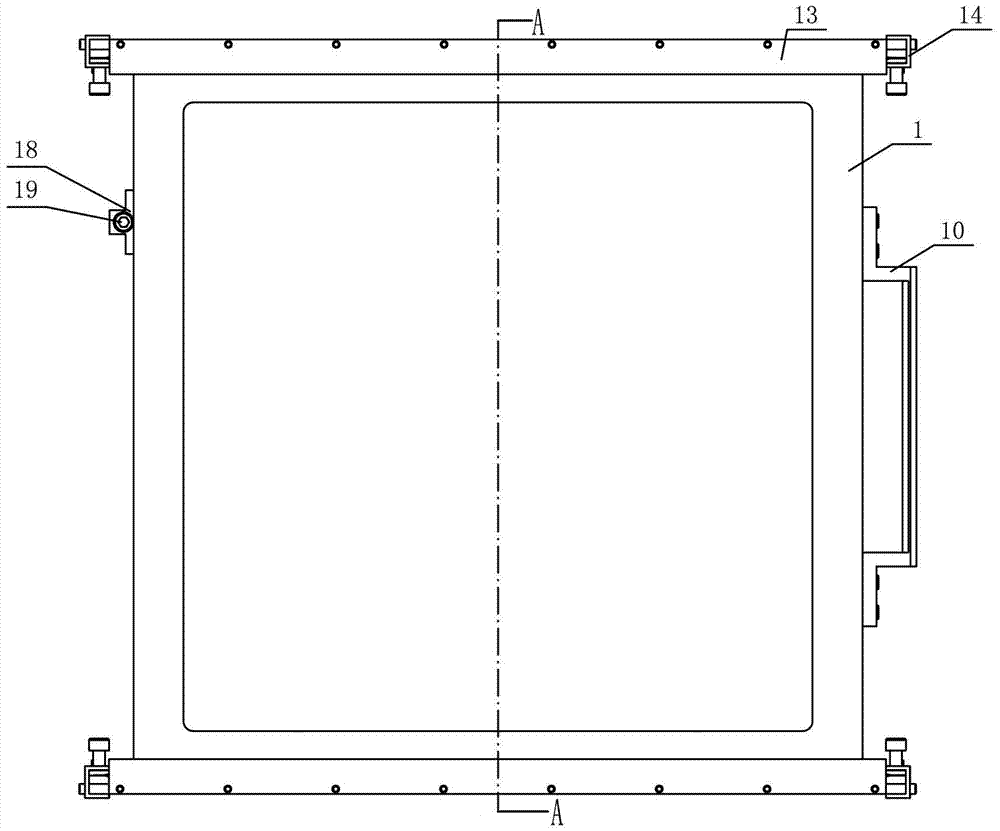
[0023] Specific implementation mode one: combine Figure 1-Figure 13 Describe this embodiment, the non-linear large-aperture optical element fast disassembly mechanism of this embodiment includes a support frame 1, a plurality of roller guide posts 2, a plurality of springs 3, a plurality of set screws 4, a plurality of roller shafts 5, a plurality of A roller 6, a plurality of roller spacers 7, four locking pieces 8, four locking piece pressing blocks 9, a handle 10, an adjustment frame 11, two bottom plates 12, two baffle plates 13, four locking Head shell 14, four locking pins 15, eight locking blocks 16, four locking screws 17, positioning blocks 18 and positioning screws 19, the upper surface 1-1 and the lower surface 1-2 of the support frame 1 1. A plurality of roller mounting holes 1-5 are provided on the top side 1-3 and the bottom side 1-4, the roller mounting holes 1-5 are blind holes, and a roller guide column 2 is housed in each roller mounting hole 1-5 , wherein ...
specific Embodiment approach 2
[0024] Specific implementation mode two: combination Figure 5 , Figure 6 , Figure 7 , Figure 9 , Figure 10 and Figure 12 Describe this embodiment, in this embodiment, the maximum distances from the outer surfaces of all the rollers 6 on the upper surface 1-1 of the support frame 1 to the upper surface 1-1 are equal, and the outer surfaces of all the rollers 6 on the bottom side 1-4 are to the bottom. Sides 1-4 have an equal maximum distance. Such setting realizes that all the rollers 6 on the lower surface 1-1 of the support frame 1 are in contact with the corresponding surfaces of the adjustment frame 11 at the same time, and all the rollers 6 on the bottom side 1-4 of the support frame 1 are in contact with the corresponding surfaces of the bottom plate 12 at the same time . Other compositions and connections are the same as in the first embodiment.
specific Embodiment approach 3
[0025] Specific implementation mode three: combination Figure 6 Describe this embodiment, the centerlines of all the roller mounting holes 1-5 respectively located on the upper surface 1-1 of the support frame 1 of this embodiment are in the same plane, and the centers of all the rollers 6 located on the upper surface 1-1 of the support frame 1 The lines are parallel to each other, the centerlines of all roller mounting holes 1-5 located on the lower surface 1-2 of the support frame 1 are in the same plane, and the centerlines of all rollers 6 located on the lower surface 1-2 of the support frame 1 are parallel to each other, located on the support frame 1. The centerlines of all the roller mounting holes 1-5 on the top side 1-3 of the frame 1 are in the same plane, the centerlines of all the rollers 6 on the top side 1-3 of the support frame 1 are parallel to each other, and are located on the bottom side 1-3 of the support frame 1 The centerlines of all roller mounting hole...
PUM
 Abstract
Description
Claims
Application Information
 - R&D
- Intellectual Property
- Life Sciences
- Materials
- Tech Scout
- Unparalleled Data Quality
- Higher Quality Content
- 60% Fewer Hallucinations
Browse by: Latest US Patents, China's latest patents, Technical Efficacy Thesaurus, Application Domain, Technology Topic, Popular Technical Reports.
© 2025 PatSnap. All rights reserved.Legal|Privacy policy|Modern Slavery Act Transparency Statement|Sitemap|About US| Contact US: help@patsnap.com


