Fast assembly and disassembly mechanism for nonlinear large-aperture optical elements

A technology of optical components and disassembly mechanism, which is applied in the direction of optical components, optics, installation, etc., can solve the problems of long time consumption and low efficiency, and achieve the effect of reducing positioning time, reducing influence and simple structure

Active Publication Date: 2013-08-07
HARBIN INST OF TECH
View PDF3 Cites 6 Cited by
  • Summary
  • Abstract
  • Description
  • Claims
  • Application Information

AI Technical Summary

Problems solved by technology

[0003] The purpose of the present invention is to solve the problems of long time consumption and low efficiency in the online replacement and installation and debugging of the existing nonlinear large-aperture optical elements, and to provide a quick disassembly and assembly mechanism for nonlinear large-aperture optical elements

Method used


Image

  • Fast assembly and disassembly mechanism for nonlinear large-aperture optical elements
  • Fast assembly and disassembly mechanism for nonlinear large-aperture optical elements
  • Fast assembly and disassembly mechanism for nonlinear large-aperture optical elements

Examples


specific Embodiment approach 1

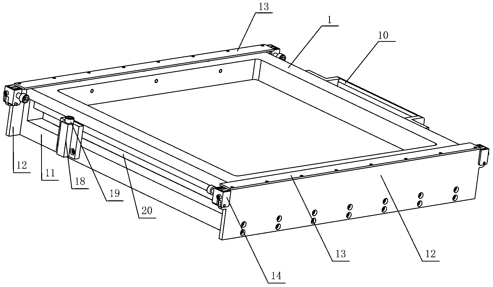
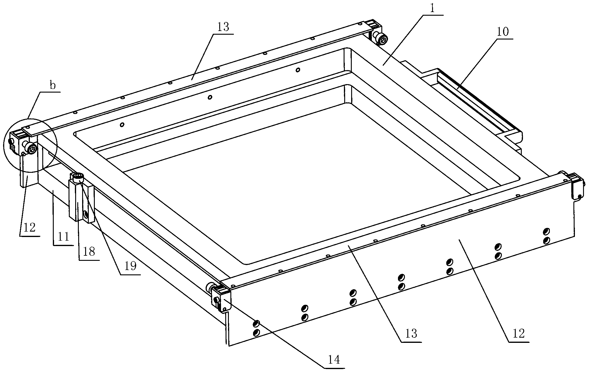
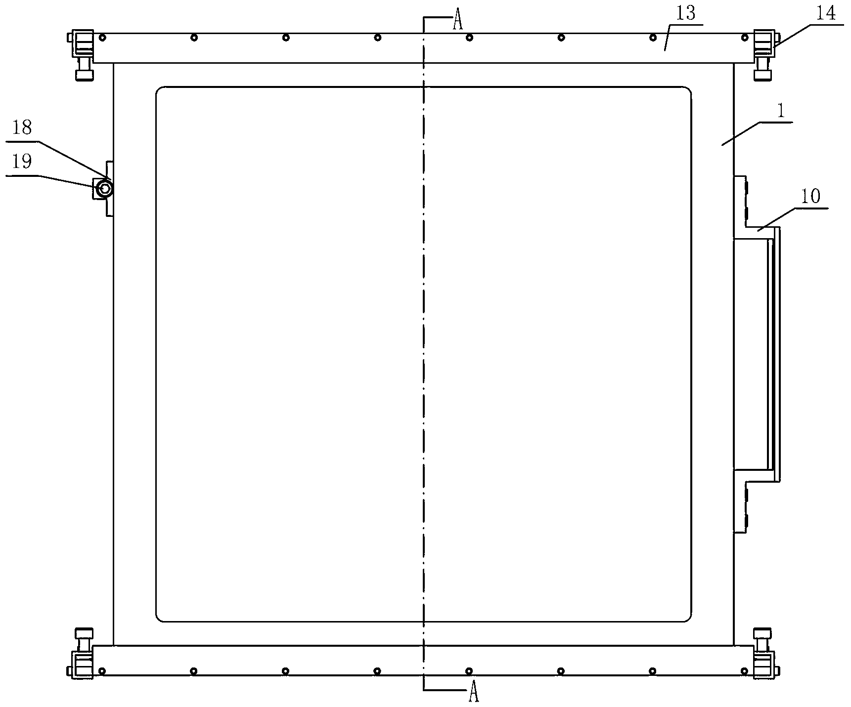
[0023] Specific implementation mode one: combine Figure 1-Figure 13 Describe this embodiment, the non-linear large-aperture optical element quick disassembly mechanism of this embodiment includes a support frame 1, a plurality of roller guide posts 2, a plurality of springs 3, a plurality of fastening screws 4, a plurality of roller shafts 5, a plurality of A roller 6, a plurality of roller spacers 7, four locking pieces 8, four locking piece pressing blocks 9, a handle 10, an adjustment frame 11, two bottom plates 12, two baffle plates 13, four locking Head shell 14, four locking pins 15, eight locking blocks 16, four locking screws 17, positioning blocks 18 and positioning screws 19, the upper surface 1-1 and the lower surface 1-2 of the support frame 1 1. A plurality of roller mounting holes 1-5 are provided on the top side 1-3 and the bottom side 1-4, the roller mounting holes 1-5 are blind holes, and a roller guide column 2 is housed in each roller mounting hole 1-5 , w...

specific Embodiment approach 2

[0024] Specific implementation mode two: combination Figure 5 , Image 6 , Figure 7 , Figure 9 , Figure 10 with Figure 12 Describe this embodiment, in this embodiment, the maximum distances from the outer surfaces of all the rollers 6 on the upper surface 1-1 of the support frame 1 to the upper surface 1-1 are equal, and the outer surfaces of all the rollers 6 on the bottom side 1-4 are to the bottom. Sides 1-4 have an equal maximum distance. Such arrangement realizes that all the rollers 6 on the lower surface 1-1 of the support frame 1 are in contact with the corresponding surfaces of the adjustment frame 11 at the same time, and all the rollers 6 on the bottom side 1-4 of the support frame 1 are in contact with the corresponding surfaces of the bottom plate 12 at the same time . Other compositions and connections are the same as in the first embodiment.

specific Embodiment approach 3

[0025] Specific implementation mode three: combination Image 6 Describe this embodiment, the centerlines of all the roller installation holes 1-5 respectively located on the upper surface 1-1 of the support frame 1 of this embodiment are in the same plane, and the centers of all the rollers 6 located on the upper surface 1-1 of the support frame 1 The lines are parallel to each other, the centerlines of all roller mounting holes 1-5 located on the lower surface 1-2 of the support frame 1 are in the same plane, and the centerlines of all rollers 6 located on the lower surface 1-2 of the support frame 1 are parallel to each other, located on the support frame 1. The centerlines of all the roller mounting holes 1-5 on the top side 1-3 of the frame 1 are in the same plane, the centerlines of all the rollers 6 on the top side 1-3 of the support frame 1 are parallel to each other, and are located on the bottom side 1-3 of the support frame 1 The centerlines of all roller mounting h...


PUM


Abstract

The invention relates to a fast assembly and disassembly mechanism for nonlinear large-aperture optical elements, which solves the problems that the time for on-line exchange and assembly debugging is long and the efficiency is low in the traditional nonlinear large-aperture optical elements. Roller mounting holes are arranged in a supporting frame, roller guide columns are arranged in the roller mounting holes, roller shafts are arranged on the roller guide columns and are provided with rollers, locking sheets are arranged on the supporting frame through locking sheet press blocks, mounting base plates are arranged on the regulating frames, baffles are arranged on the base plates, locking head shells are arranged on the base plates, the base plates, the locking head shells and locking blocks are connected by locking pins, the regulating frame is provided with a locating block, a locating bolt is arranged in the locating block, the rollers are connected with the regulating frame, the base plates and the baffles, the supporting frame is connected with the locating bolt, the locking sheets are inserted between the locking blocks, and locking bolts are connected with the locking blocks. The fast assembly and disassembly mechanism disclosed by the invention is applied to on-line exchange and assembly debugging experiments of the nonlinear large-aperture optical elements.

Description

technical field [0001] The invention relates to an optical element disassembly mechanism, in particular to a nonlinear large-diameter optical element quick disassembly mechanism. Background technique [0002] The nonlinear large-aperture optical components used in the field of laser nuclear fusion undertake the task of high-energy laser harmonic conversion. During work, large-aperture optical components need to be replaced, installed and debugged online, and the precise installation of large-aperture optical components must be ensured position. In the prior art, the support frame and the adjustment frame are in surface contact, which takes a long time for installation and commissioning, and the efficiency is low. A reasonably designed disassembly mechanism is used for online replacement, installation and commissioning of large-diameter optical components, which can reduce the installation and commissioning time ,Improve work efficiency. Contents of the invention [0003]...

Claims


Application Information

Patent Timeline
Patent Type & Authority Applications(China)
IPC IPC(8): G02B7/00
Inventor 梁迎春于福利卢礼华苏瑞峰张庆春
Owner HARBIN INST OF TECH
Why Eureka
Try Eureka