Spring pin pushing device

A pusher and internal insulation technology, applied in the direction of overhead line/cable equipment, etc., can solve the problems of poor accuracy, high proficiency, damage to insulators, etc., and achieve the effect of improving operation accuracy and simple use.

Active Publication Date: 2013-08-07
STATE GRID CORP OF CHINA +1
View PDF5 Cites 6 Cited by
  • Summary
  • Abstract
  • Description
  • Claims
  • Application Information

AI Technical Summary

Problems solved by technology

[0002] The traditional electrified pin remover is usually a piece of flat metal, which is installed on the head of the insulating rod. The purpose of removing the spring M pin in the bowl head is achieved by hitting the metal plate on the head of the insulating rod. This method not only Poor accuracy, high proficiency required
It is also very easy to damage the insulator during the knocking process, or directly break and fly the spring M pin

Method used


Image

  • Spring pin pushing device
  • Spring pin pushing device
  • Spring pin pushing device

Examples


Embodiment Construction

[0013] Below in conjunction with accompanying drawing, the present invention is described in further detail:

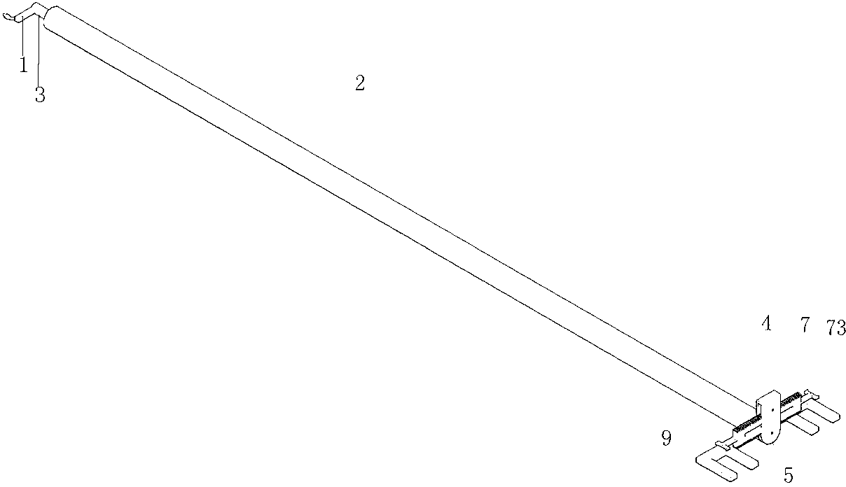
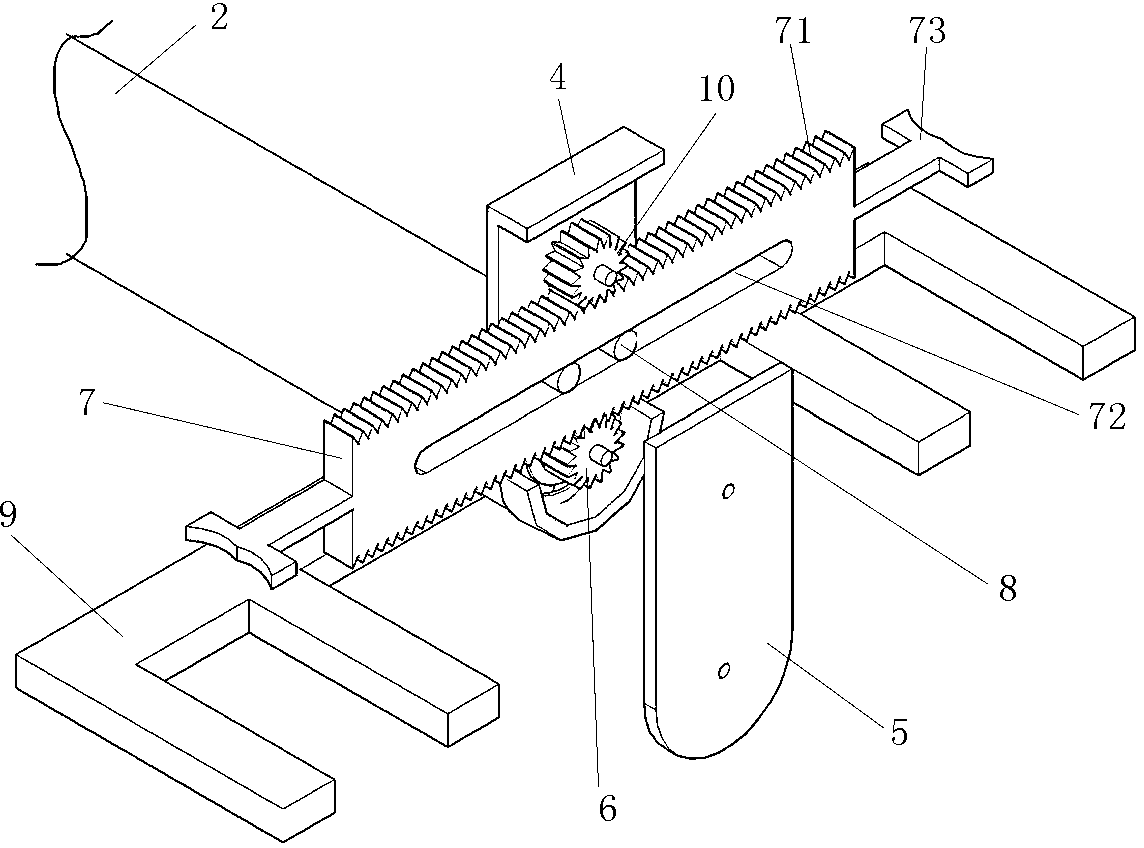
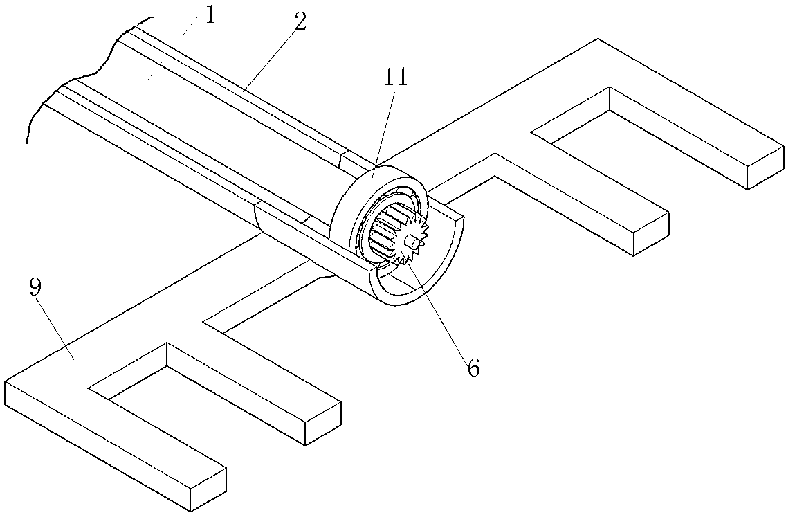
[0014] Such as Figure 1-3 As shown, the spring pusher of the present invention includes an inner insulating rod 1 and an outer insulating rod 2, the inner insulating rod 1 is sleeved in the outer insulating rod 2, and each of the head and tail parts of the inner insulating rod 1 is equipped with a matching outer insulating rod 1. Bearing 11, because bearing is installed between the two layers of insulating rods, the inner layer insulating rods rotate flexibly and smoothly. The lower part of the head end of the outer insulating rod 2 is fixedly connected with the bowl head slot plate 9 by screws. The bowl head slot plate 9 is composed of two symmetrical F-shaped plates. The upper part of the outer insulating rod 2 head end is connected to the inner cover Plate 4 is fixedly connected and is mainly used to support all components. The inner cover 4 is provided with...


PUM


Abstract

The invention relates to a spring pin pushing device. The device comprises an inner insulation rod and an outer insulation rod, wherein the outer insulation rod is fixedly connected with a socket clamping trough plate and an inner cover plate; a track location column is arranged on the inner cover plate; an upper gear is respectively connected with the inner cover plate and an outer cover plate; a lower gear is respectively connected with the outer cover plate and the inner insulation rod; the tail end of the inner insulation rod is connected with a crank; a pin pushing plate is arranged between the upper and lower gears; the left and right sides of the pin pushing plate are respectively connected with a crescent groove; the upper and lower ends of the pin pushing plate are respectively provided with gear teeth which are fit with the upper and lower gears; a strip-type hole is formed in the middle part of the pin pushing plate; and the pin pushing plate is inserted into the track location column through the strip-type hole and is kept rolling along a horizontal direction through the track location column. A mechanical driving force is adopted to replace an original human perception pin pushing method and directly acts on a spring M pin, so that the operation accuracy is greatly improved; and the spring pin pushing device is simple to use and cannot generate a phenomenon that the spring M pin is directly beaten away.

Description

technical field [0001] The invention relates to a spring pusher for taking out an insulator bowl head spring M pin with electricity. Background technique [0002] The traditional electrified pin remover is usually a piece of flat metal, which is installed on the head of the insulating rod. The purpose of removing the spring M pin in the bowl head is achieved by hitting the metal plate on the head of the insulating rod. This method not only Poor accuracy, high proficiency required. It is also very easy to damage the insulator during the knocking process, or directly damage and fly the spring M pin. Contents of the invention [0003] The technical problem to be solved by the present invention is to provide a spring pusher, which is easy to use and has high safety. [0004] In order to solve the problems existing in the prior art, the technical solution adopted in the present invention is: [0005] The spring pusher includes an inner insulating rod, an outer insulating rod...

Claims


Application Information

Patent Timeline
Patent Type & Authority Applications(China)
IPC IPC(8): H02G1/02
Inventor 张森王鲁杜东高张海忱王景泉赵德仁宋宝忠许晓夏宗泽葛洪光
Owner STATE GRID CORP OF CHINA
Why Eureka
Try Eureka