
Injection molding machine testing mold and device

A technology for injection molding machines and molds, applied in the field of injection molding machine testing devices, can solve problems such as time-consuming, difficult to achieve predetermined functions of pressurized cylinders, and strengthening tie rods, etc., to achieve accurate and convenient testing effects

Active Publication Date: 2013-08-14
HAITIAN PLASTICS MACHINERY GRP
View PDF4 Cites 3 Cited by
  • Summary
  • Abstract
  • Description
  • Claims
  • Application Information

AI Technical Summary

Problems solved by technology

Existing testing devices for injection molding machines use low-load, non-destructive conventional test methods such as standard blocks in the testing process, which is time-consuming, inefficient, and the reliability of the test results is poor. Therefore, various extreme working conditions must be simulated for destructive testing. , one of the most prominent is to design a mold with the same expansion effect as the real mold to strengthen the deformation of the tie rod, and evaluate its fatigue performance and service life more quickly
Due to the limitation of the inner spacing of the tie rods and the thickness of the mold, it is difficult for ordinary pressurized cylinders to achieve the intended function, so it is necessary to design a mold for injection molding machine testing and its corresponding testing device for injection molding machines

Method used


Image

  • Injection molding machine testing mold and device
  • Injection molding machine testing mold and device
  • Injection molding machine testing mold and device

Examples


Embodiment Construction

[0021] Below in conjunction with accompanying drawing embodiment to this invention for further description.

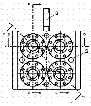
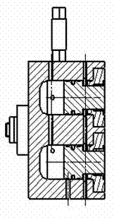
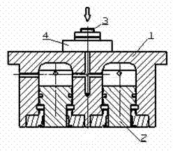
[0022] like figure 1 , Figure 2, image 3 , as shown in Figure 4, the mold for injection molding machine testing includes cavity body 1, pusher piston 2, ejector piston 3, ejector piston cover 4, pusher piston cover 5, high pressure resistant seal 6, guide belt 7, Check valve 8.

[0023] Die pushing piston 2 is placed on die cavity main body 1 side, and is fixed by pushing die piston cover 5, forms pushing die oil cylinder.

[0024] The ejector rod piston 4 is placed on the other side of the mold cavity main body 1, and is fixed by the ejector rod piston cover 4 to form an ejector rod oil cylinder.

[0025] The rodless chamber of the mold pushing cylinder communicates with the rodless chamber of the ejector cylinder, and the rodless chamber of the mold pushing cylinder is fed into and controlled by the high pressure resistant one-way valve 8.

[0026] The cylinde...


PUM


Abstract

The invention discloses an injection molding machine testing mold. The mold comprises a mold main body, wherein a small oil cavity and a large oil cavity are arranged on the two sides inside the mold main body respectively, mold pushing cylinders are arranged inside the large oil cavity, an ejector pin cylinder is arranged inside the small oil cavity, an ejector pin piston of the ejector pin cylinder is in butt-joint with the head part of a screw, the mold pushing cylinders are communicated with the ejector pin cylinder through passages and are communicated with an oil inlet passage, and a one-way valve is arranged in the oil inlet passage. The invention also provides an injection molding machine testing device comprising the injection molding machine testing mold and the screw of an injection mechanism, wherein the ejector pin piston of the ejector pin cylinder and the head part of the screw are in butt-joint, and the oil inlet passage of the injection molding machine testing mold is connected with an original oil liquid system of the injection molding machine. The testing device can simulate the strain situation of a mold locking mechanism and especially the strain situations of a molding plate and a draw bar under extreme conditions, and can accurately and conveniently test the fatigue resistances of the molding plate and the draw bar.

Description

technical field [0001] The invention relates to a testing tool for an injection molding machine, and also relates to a testing device for an injection molding machine. Background technique [0002] The work of the mold clamping mechanism of the injection molding machine is a process of reciprocating and alternating stress. The tie rod is the largest bearer of the mold clamping deflection and has a major impact on the stiffness of the mold clamping mechanism. Fatigue life and reliability are the most important performances of the tie rod. It is the focus of attention of the plastic machine industry and users. Due to the many factors involved in the performance of tie rods and the basic research on fatigue life theory and failure mechanism, etc., the fatigue life test is undoubtedly the only effective way to evaluate this index. Existing testing devices for injection molding machines use low-load, non-destructive conventional test methods such as standard blocks in the testin...

Claims


Application Information

Patent Timeline
Patent Type & Authority Applications(China)
IPC IPC(8): B29C45/67B29C45/26
Inventor 史天瑜吴章成
Owner HAITIAN PLASTICS MACHINERY GRP
Learn More