Motor transmission shaft torsion testing tool

A technology of torque testing and motor transmission, applied in measuring devices, force/torque/work measuring instruments, instruments, etc., can solve problems such as lack of testing equipment, difficult testing, etc.

Inactive Publication Date: 2012-05-02
许晓华
View PDF4 Cites 1 Cited by
  • Summary
  • Abstract
  • Description
  • Claims
  • Application Information

AI Technical Summary

Problems solved by technology

However, after the Belleville spring gear assembly 4 is processed, it is difficult to te

Method used


Image

  • Motor transmission shaft torsion testing tool
  • Motor transmission shaft torsion testing tool

Examples


Embodiment Construction

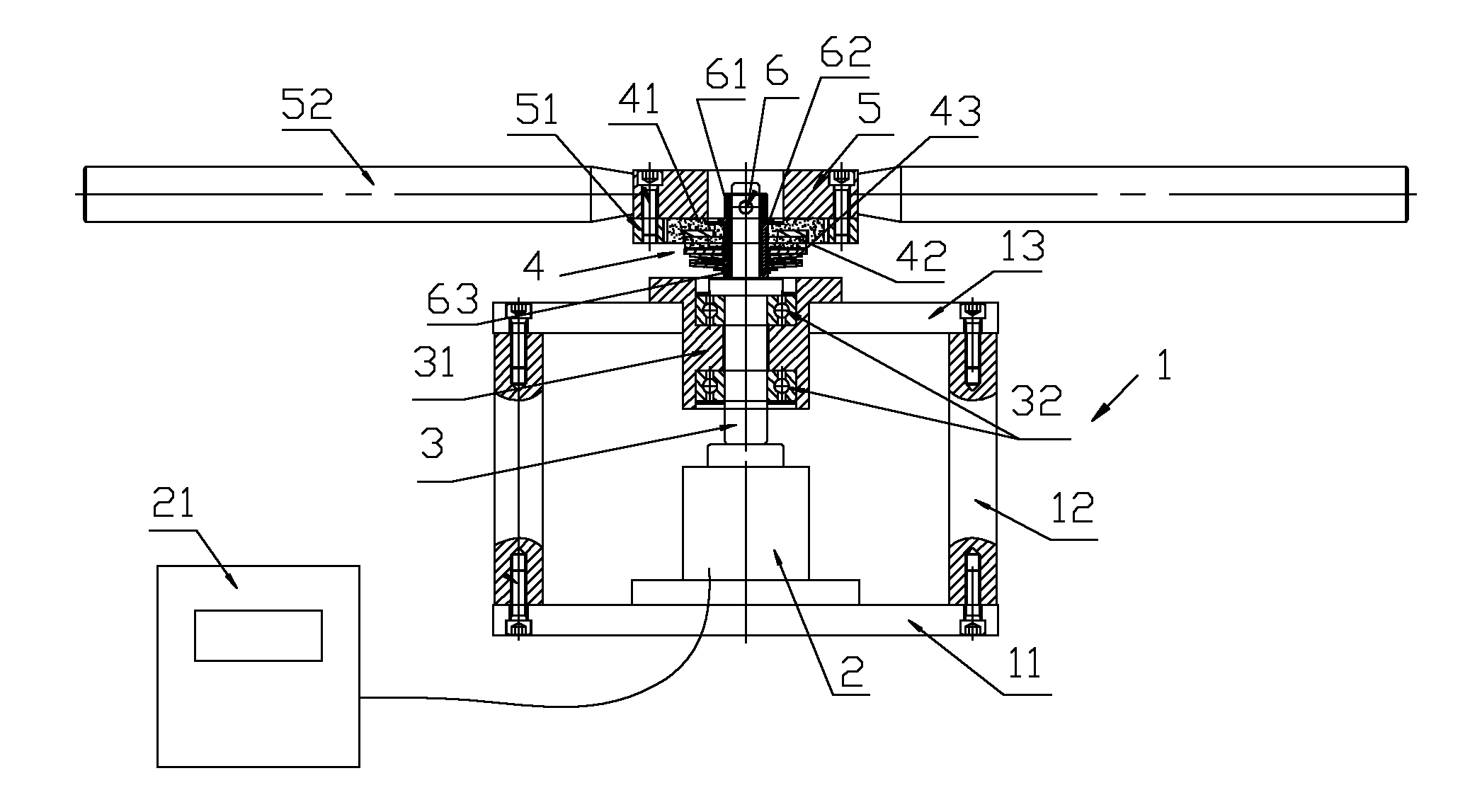
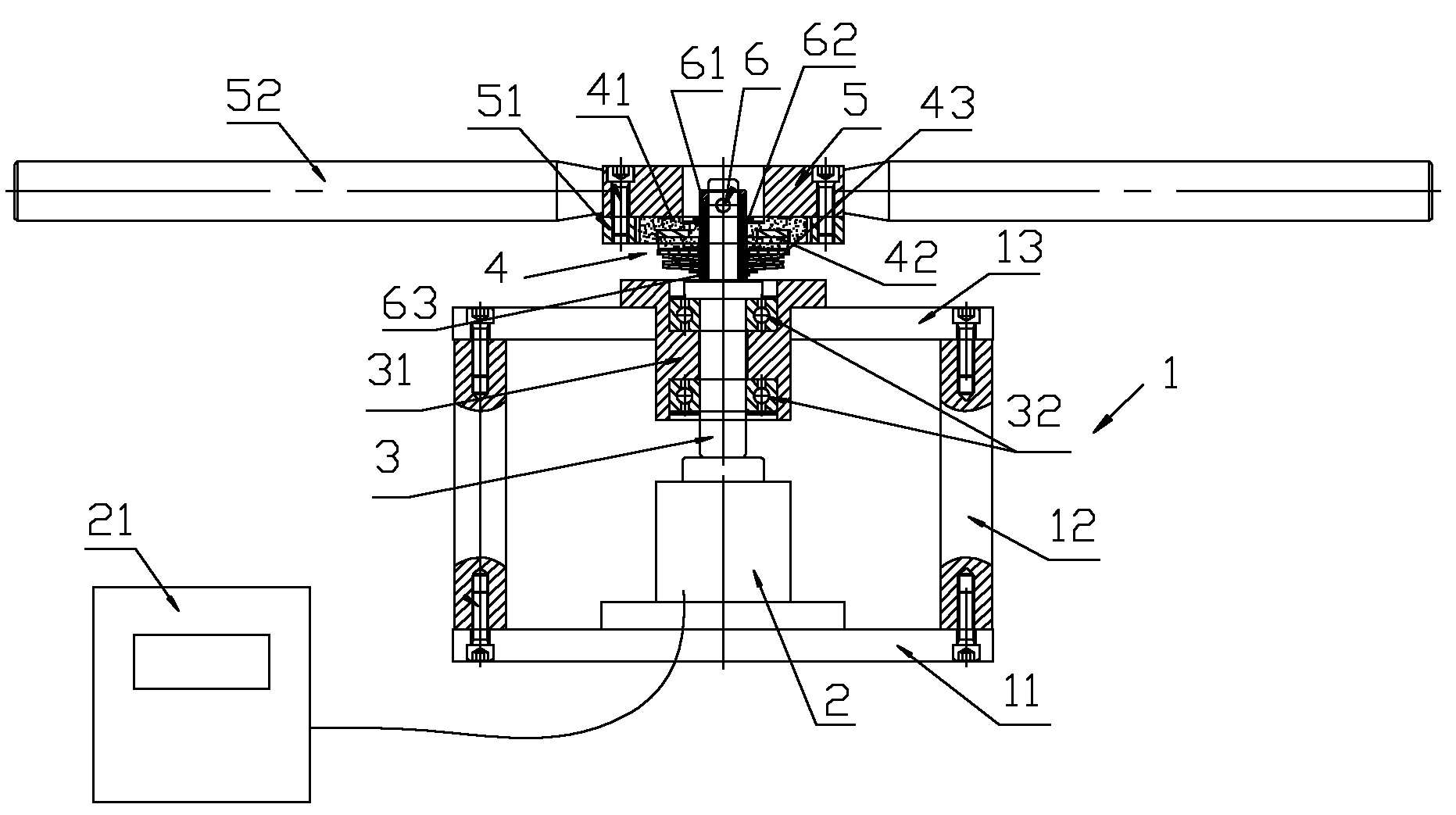
[0012] Such as figure 1 As shown, it is an embodiment of the motor transmission shaft torsion test tooling of the present invention, including a frame 1, on which a transmission connecting shaft 3 is arranged for vertical rotation, and a torque sensor 2 is provided at the bottom of the frame, and the torque sensor passes through a signal line It is connected with the digital torque display instrument 21, the lower end of the transmission connection shaft is connected with the torque sensor, the upper end of the transmission connection shaft extends out of the frame and is sleeved with the butterfly spring gear assembly 4, and the gear 41 of the butterfly spring gear assembly is provided with a The rotating mechanism drives the gears to rotate. The rotating mechanism includes a locating ring 5, and the fixed outer ring is provided with a test handle 52 that drives the locating ring to rotate. The lower part of the locating ring is fixed with a test ring gear 51. gears meshing....


PUM


Abstract

The invention discloses a motor transmission shaft torsion testing tool, which comprises a frame, wherein a transmission connecting shaft is vertically and rotatably arranged on the frame; a torsion sensor is arranged at the lower part of the frame; the torsion sensor is connected with a digital torsion display instrument through a signal wire; the lower end of the transmission connecting shaft is connected with the torsion sensor, and the upper end of the transmission connecting shaft extends out of the frame and is sleeved with a belleville spring gear assembly; and a rotating mechanism is arranged outside a gear of the belleville spring gear assembly and is used for driving the gear to rotate. The motor transmission shaft torsion testing tool disclosed by invention is simple in structure, and convenient and accurate in testing.

Description

technical field [0001] The invention relates to a tool for testing the torsion of a motor transmission shaft. Background technique [0002] The butterfly spring gear assembly 4 is installed on the motor transmission shaft to protect the excessive torque of the motor transmission shaft, such as figure 1 As shown, the Belleville spring gear assembly includes a shaft sleeve 61, the shaft sleeve and the transmission shaft are fixed by a fixed pin 6, the upper outer circumference of the shaft sleeve is provided with a ring of protrusions 62, and the lower outer circumference of the shaft sleeve The ring is provided with a circle of grooves, and a retaining ring 63 is arranged in the groove, a gear 41 and a butterfly spring 43 are arranged between the protrusion on the bushing and the retaining ring, and the gear is provided with a friction body 42 and a butterfly spring. The spring is in contact, and a retaining ring is also provided between the bushing protrusion 62 and the gea...

Claims


Application Information

Patent Timeline
IPC IPC(8): G01L5/00
Inventor 陈永飞
Owner 许晓华
Why Eureka
Try Eureka