Punching device for electromagnetic punching machine

A stamping device and stamping machine technology, which is applied in the field of components on electromagnetic stamping machines, can solve the problems of small stamping force and unstable stamping force, and achieve the effects of large stamping force, stable stamping force and short action time

Active Publication Date: 2014-12-17
汕头市开达实业有限公司
View PDF8 Cites 0 Cited by
  • Summary
  • Abstract
  • Description
  • Claims
  • Application Information

AI Technical Summary

Problems solved by technology

[0003] In order to overcome the disadvantages of unstable punching force and small punching force of existing electromagnetic punching machines, the present invention provides a punching device for electromagnetic punching machines, which has stable punching force and large punching force Features, expanding the range of stamping workpieces

Method used


Image

  • Punching device for electromagnetic punching machine
  • Punching device for electromagnetic punching machine
  • Punching device for electromagnetic punching machine

Examples


Embodiment Construction

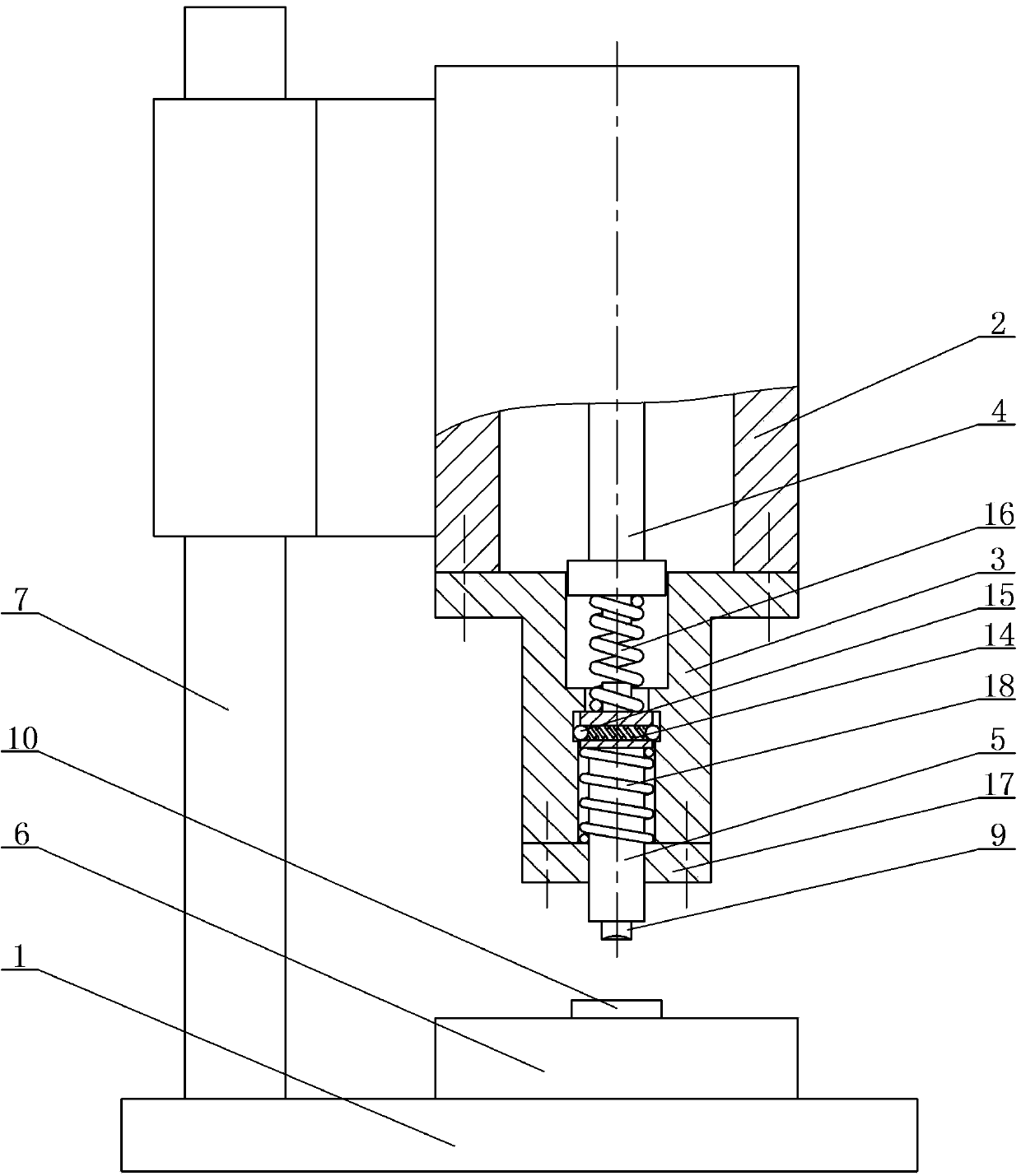
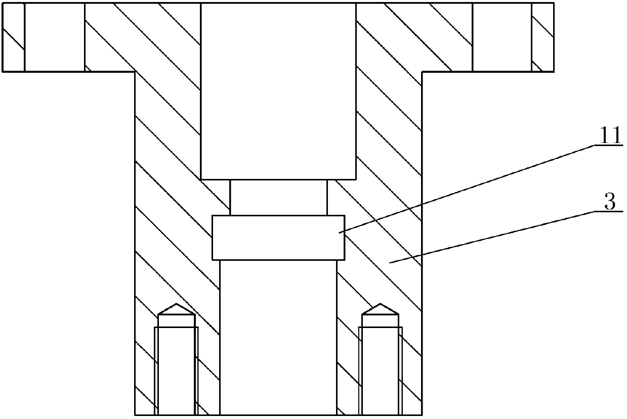
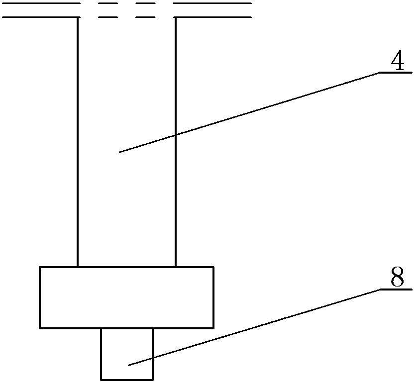
[0012] The present invention will be further described below in conjunction with accompanying drawing:

[0013] Depend on figure 1 combine figure 2 , image 3 , Figure 4 As shown, a stamping device used on an electromagnetic stamping machine includes a base 1, an installation sleeve 2, a punch seat 3, a stamping rod 4 and a punch 5, a workbench 6 and a column 7 are arranged on the base 1, and the installation sleeve The cylinder 2 is installed on the column 7 and can be adjusted up and down. The lower end of the installation sleeve 2 is connected with the punch seat 3, the punch 5 is located in the punch seat 3, the lower part of the punch 5 is connected with the upper mold 9, and the working table 6 is equipped with a The upper mold 9 corresponds to the lower mold 10, the center of the punch seat 3 is provided with a stepped hole that penetrates up and down, the inner wall of the punch seat 3 is provided with an annular groove 11, and the punch 5 is provided with a hole ...


PUM


Abstract

A punching device for an electromagnetic punching machine mainly solves the problem that the existing electromagnetic punching machine is instable and small in punching pressure. The punching device is characterized in that a vertical-through step hole is arranged at the center of a punch seat (3), an annular groove (11) is arranged on the inner wall of the punch seat (3), a boss (12) corresponding to the annular groove (11) is arranged on a punch (5), a radial-through through hole (13) is arranged on the boss (12), a clamping spring (14) and steel balls (15) are built in the through hole (13), the two steel balls are arranged at two ends of the clamping spring (14) respectively, and a resetting spring (18) is arranged between the lower portion of the boss (12) and an end cover (17). The punching device for the electromagnetic punching machine has the advantages of being stable and large in punching pressure and expanding the punching range of workpieces.

Description

technical field [0001] The invention relates to a component on an electromagnetic punching machine, in particular to a punching device used on an electromagnetic punching machine. Background technique [0002] Electromagnetic punching machine is a punching device that uses the magnetic attraction force generated by the electromagnet coil as the power. Because of its compact structure, small size and simple operation, it is widely used in metal stamping, cutting, riveting, etc. The existing electromagnetic stamping machine is mainly composed of a base, an electromagnetic coil, a static armature, a moving armature, a stamping rod and a punch. There is an electromagnetic coil and a static armature inside. The movable armature is fixed to the stamping rod and is located above the static armature. The stamping rod passes through the center of the electromagnetic coil and its lower end corresponds to the punch. The lower end of the installation sleeve is connected to the punch sea...

Claims


Application Information

Patent Timeline
Patent Type & Authority Patents(China)
IPC IPC(8): B30B15/00B30B1/42
Inventor 陈少梅
Owner 汕头市开达实业有限公司
Why Eureka
Try Eureka