Pressure regulating variable flow water saving device

A technology of water-saving devices and pressure regulators, which is applied to water supply devices, water supply main pipelines, water supply pipeline systems, etc., can solve problems such as limited water demand, and achieve the effects of simple structure, automatic adjustment of pressure and flow, and convenient installation

Inactive Publication Date: 2015-08-19
HUNAN UNIV OF SCI & TECH
View PDF5 Cites 2 Cited by
  • Summary
  • Abstract
  • Description
  • Claims
  • Application Information

AI Technical Summary

Problems solved by technology

The structure of the diaphragm type direct-acting pressure reducing valve is to realize the pressure reducing function by overcoming the force of the spring under the pressure of the diaphragm; Pressure water saving purpose, but limited water demand after pressure regulation

Method used


Image

  • Pressure regulating variable flow water saving device
  • Pressure regulating variable flow water saving device

Examples


Embodiment Construction

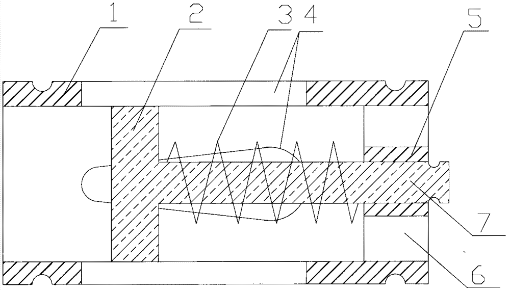
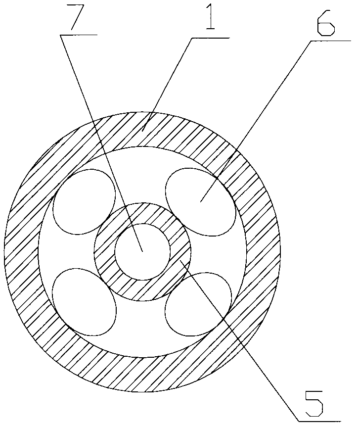
[0015] See attached figure 1 And attached figure 2 , a pressure-regulating and variable-flow water-saving device, including a groove sleeve, a piston and a spring 3, the groove sleeve is a cylindrical shell, a piston is installed in the groove sleeve, the groove sleeve includes a sleeve 1 and a support frame 5, the sleeve 1 One end is a through hole, and the other end is provided with a support frame 5 with a water outlet 6. The center of the support frame 5 is a through hole. The side wall of the sleeve 1 is provided with a number of slots 4. The piston includes a piston plate 2 and a piston rod 7. Piston plate 2 divides the groove hole into front and rear parts. Piston plate 2 slides and fits with the inner wall of sleeve 1. Piston rod 7 slides and fits with the inner hole of support frame 5. Piston and groove sleeve can slide relatively. On the piston rod 7 between the piston plate 2 and the support frame 5, the two ends of the spring 3 are respectively connected to the e...


PUM


Abstract

The invention relates to a pressure-regulating variable-flow water economizer which comprises a groove sleeve, a piston and a spring. The groove sleeve is a cylindrical shell. The piston is mounted in the groove sleeve. The groove sleeve comprises a sleeve and a support frame. One end of the sleeve is a through hole. The other end of the sleeve is provided with the support frame with a water outlet. The side wall of the sleeve is provided with a plurality of slots. The piston comprises a piston piece and a piston rod. The piston piece is slidably matched with a sleeve inner wall combining face. The piston rod is slidably matched with a support frame inner hole combining face. The piston and the groove sleeve can slide relative to each other. The spring is sleeved on the piston rod between the piston piece and the support frame. Two ends of the spring are respectively in contact connection with an end faces of each of the piston piece and the support frame. By the groove sleeve with the slots and the piston and spring mounted in the groove sleeve, the defects such as flow loss and pressure loss caused by front-rear end pressure difference of the existing water economizers can be overcome, and pressure and flow can be adjusted automatically. The water economizer is applicable to fields such as building water supply.

Description

technical field [0001] The invention relates to a water-saving device, in particular to a mechanical automatic pressure-regulating and variable-flow water-saving device. Background technique [0002] At present, diaphragm-type direct-acting pressure reducing valves and constant-pressure and constant-flow water-saving devices are generally used to solve the problem of excessive water supply pressure caused by building floor differences. The structure of the diaphragm type direct-acting pressure reducing valve is to realize the pressure reducing function by overcoming the force of the spring under the pressure of the diaphragm; Pressure water saving purpose, but limited the water demand after pressure regulation. Contents of the invention [0003] The object of the present invention is to provide a pressure-regulating-variable-flow water-saving device that can automatically adjust the cross-sectional area to realize pressure-reducing and variable-flow. [0004] The object ...

Claims


Application Information

Patent Timeline
Patent Type & Authority Patents(China)
IPC IPC(8): F16K17/30E03B7/09
Inventor 赵正江吴毅君姚晓军杨焰张义军
Owner HUNAN UNIV OF SCI & TECH
Why Eureka
Try Eureka