
Valve plug

A technology of valve seat and switching valve, applied in the direction of valve details, diaphragm valve, valve device, etc., can solve the problems of system failure, valve can not be reversibly connected to the substrate, etc.

Active Publication Date: 2013-08-14
BURKERT WERKE +1
View PDF8 Cites 14 Cited by
  • Summary
  • Abstract
  • Description
  • Claims
  • Application Information

AI Technical Summary

Problems solved by technology

However, the disadvantage of parallel fabrication and integration is that the valve cannot be connected to the substrate in a reversible manner.
So the failure of a single valve means the failure of the whole system

Method used


Image

  • Valve plug
  • Valve plug
  • Valve plug

Examples


Embodiment Construction

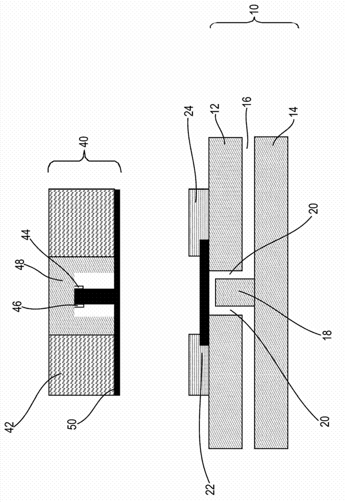
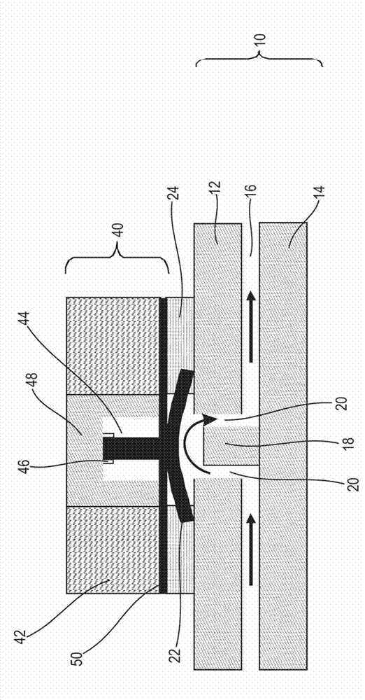
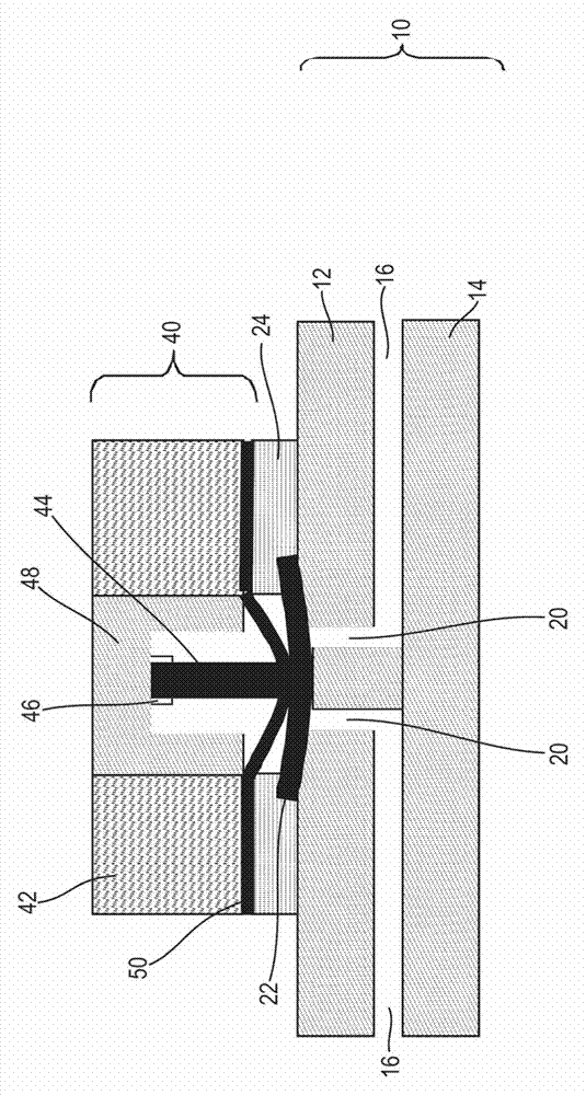
[0050] figure 1 A base plate 10 configured as a fluid switching plate is shown. The base plate 10 comprises two thin polymer plates 12, 14 between which a fluid conduit 16 is arranged. The fluid conduit 16 is interrupted at various points (cf. stop 18 ) and at these points a through hole 20 is provided in one of the plates (here plate 12 ) so that the fluid conduit can be on both sides of the stop 18 Connect to each other in a controlled manner.

[0051] A seal 22 adapted to cooperate with a stop 18 which then serves as a valve seat is arranged in the region of the through hole 20 . The seal / switching diaphragm 22 is arranged in a steel disc 24 which due to its properties acts as a soft magnetic retainer. The seal or switching diaphragm 22 is clamped in particular to the inner circumference of the steel disc 24 formed below its shoulder, ensuring a seal on the upper surface of the plate 12 in the region of the through hole 20 .

[0052] The movable fluid part 40 , here con...


PUM


Abstract

An active fluid component (40) for connection with a substrate (10) has an interface which can be connected with the substrate (10) in a fluid-tight manner, and a magnet (42) arranged in the region of the interface.

Description

technical field [0001] The invention relates to a movable fluid component connectable to a substrate. The invention also relates to an assembly having a base plate and a fluidic component. The invention relates in particular to the field of large-scale integrated microfluidics, in which different fluidic conduits, branches, couplings, mixer structures or the like are arranged in a substrate (also called a fluidic chip). Background technique [0002] Large-scale integrated microfluidic chips are particularly suitable for selectively examining or analyzing very small fluid volumes. The substrates used here can be manufactured at low cost and with high precision, and only small amounts of reagent or sample material are necessary for the analysis, which results in a highly efficient analysis. After this analysis, the substrates were processed to avoid cross-contamination between different samples. [0003] To date, moving fluid components, such as valves or pumps, could not b...

Claims


Application Information

Patent Timeline
Patent Type & Authority Applications(China)
IPC IPC(8): F16K31/00F16K31/06F16K31/70F16K7/16
CPCF16K31/025F16K99/0015B01L2400/0616F16K99/0038F16K31/08F16K99/00B01L3/502738F16K99/0044B01L2400/0633B01L3/5027B01L3/50273Y10T137/2213Y10T137/2224
Inventor 马尔科·布拉默克里斯托夫·梅尼安
Owner BURKERT WERKE
Learn More