
Adapting connector

A technology of transfer connectors and connectors, which is applied in the direction of connection, parts of connection devices, protective grounding/shielding devices of connection parts, etc., which can solve the problems of increasing production costs

Inactive Publication Date: 2013-08-14
泗阳万旭电子元件有限公司
View PDF4 Cites 5 Cited by
  • Summary
  • Abstract
  • Description
  • Claims
  • Application Information

AI Technical Summary

Problems solved by technology

[0002] The currently known transfer connector structure mainly includes a printed circuit board connected to two connectors of different specifications. In order to avoid noise interference, a metal isolation cover is often provided outside the printed circuit board in the transfer connector. Generally, The method is to set the extended positioning column on the printed circuit board as a positioning function, and then lock the isolation cover to the support, or make the edge of the printed circuit board to match the edge shape of the isolation cover and use it as the isolation cover. However, whether it is adding a positioning column or making a shape, it will increase the production cost

Method used


Image

  • Adapting connector
  • Adapting connector
  • Adapting connector

Examples


Embodiment Construction

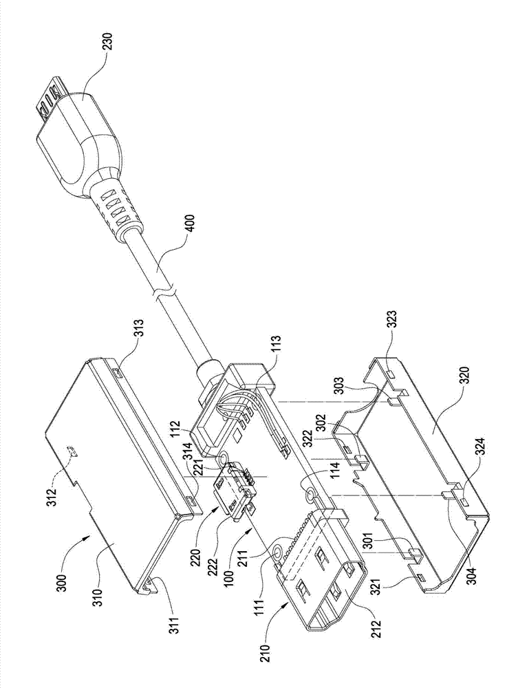
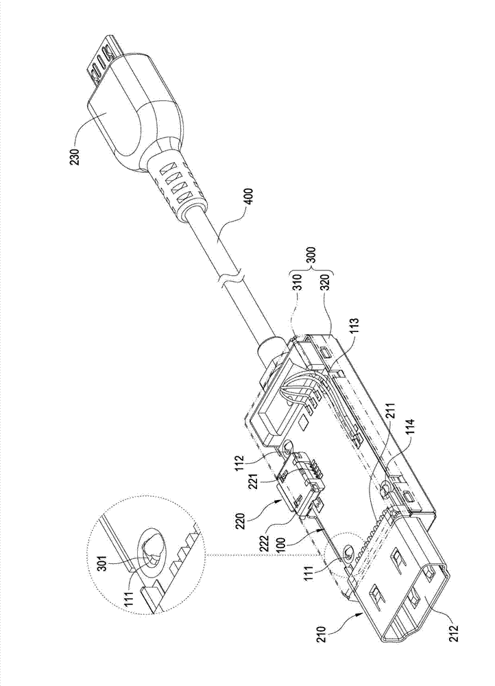
[0038] refer to figure 1 , The first embodiment of the present invention provides a transfer connector, which includes: a circuit board 100 , two first connectors 210 / 220 , a second connector 230 , a metal shell 300 and a cable 400 .

[0039] A transfer circuit is preferably printed on the surface of the circuit board 100 in the form of a printed circuit, and the transfer circuit is used to convert signals of different specifications between the first connector 210 / 220 and the second connector 230 . The circuit board 100 is preferably provided with four positioning holes 111 / 112 / 113 / 114 (this invention does not limit the number of positioning holes), and each positioning hole 111 / 112 / 113 / 114 is electrically connected to the ground line.

[0040] In this embodiment, the transfer connector of this invention preferably includes two first connectors 210 / 220 (this invention does not limit the number of first connectors), these first connectors 210 / 220 preferably Different spe...


PUM


Abstract

An adapting connector comprises a circuit board, at least one first connector and a metal shell. The circuit board comprises an adapting circuit, each first connector comprises a plurality of weld legs, and the weld legs are welded on the circuit board and are electrically connected with the adapting circuit. The metal shell covers on the circuit board, shades the weld legs and the adapting circuit, and comprises at least one positioning pin that is welded on the circuit board.

Description

technical field [0001] The invention relates to a transfer connector, especially a transfer connector with a metal shell grounding positioning pin. Background technique [0002] The currently known transfer connector structure mainly consists of a printed circuit board connected to two connectors of different specifications. In order to avoid noise interference, a metal isolation cover will be provided outside the printed circuit board in the transfer connector. Generally, The method is to set the extended positioning column on the printed circuit board as a positioning function, and then lock the isolation cover to the support, or make the edge of the printed circuit board to match the edge shape of the isolation cover and use it as the isolation cover. However, whether it is adding a positioning column or making a shape, the production cost will be increased. Contents of the invention [0003] One purpose of the present invention is to provide a transfer connector, whic...

Claims


Application Information

Patent Timeline
Patent Type & Authority Applications(China)
IPC IPC(8): H01R31/06H01R13/648H01R13/66
Inventor 李权洲刘赐堂林展列叶士敦
Owner 泗阳万旭电子元件有限公司
Learn More