Noise-suppression circuit provided with blocking capacitor of audio amplifier

A technique for suppressing circuits and controlling circuits, applied in the direction of frequency response correction, etc.

Active Publication Date: 2013-08-14
ANYKA (GUANGZHOU) MICROELECTRONICS TECH CO LTD
View PDF6 Cites 18 Cited by
  • Summary
  • Abstract
  • Description
  • Claims
  • Application Information

AI Technical Summary

Problems solved by technology

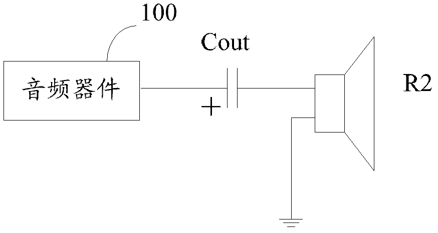
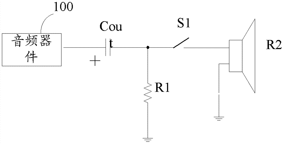
[0007] In view of this, the present invention provides a kind of audio power amplifier noise suppression circuit with isolation straight capacitor, to overcome the THD (Total Harmonic Distortion) index of reducing audio signal and the effective drive ability of audio frequency power amplifier in the prior art and eliminate Noise, or the problem of eliminating noise at the cost of sacrificing the power-on and power-off time of the chip (generally 300mS~1S)

Method used


Image

  • Noise-suppression circuit provided with blocking capacitor of audio amplifier
  • Noise-suppression circuit provided with blocking capacitor of audio amplifier
  • Noise-suppression circuit provided with blocking capacitor of audio amplifier

Examples


Embodiment 2

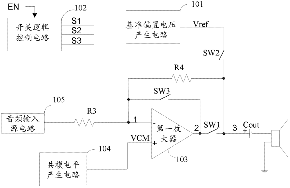
[0096] Reference Bias Voltage V ref It is the reference source of all bias voltages, and the accuracy is very high (generally, it will be fine-tuned by trimming). Except for circuits with particularly demanding performance requirements, it is generally not allowed to directly use the reference bias voltage V ref as a reference source. Therefore, the method of this embodiment is to directly obtain the bias source from the power supply voltage VCC through proportional resistor voltage division.

[0097] see Figure 9 , is a schematic diagram of the second audio power amplifier noise suppression circuit with an isolated direct capacitor disclosed by the present invention, the reference bias voltage V in the circuit ref The generating circuit, the switching logic control circuit 901 and the common mode level VCM generating circuit 902 are different from those in the first embodiment, and the others are the same, and on this basis, it also includes: a power supply VCC, a third r...


PUM


Abstract

The invention discloses a noise-suppression circuit provided with a blocking capacitor of an audio amplifier. The noise-suppression circuit comprises a reference bias voltage Vref generation circuit, a switch logic control circuit, a first amplifier, a first proportion feedback resistor R3, a second proportion feedback resistor R4, a common mode level VCM generation circuit, an audio input source circuit, the blocking capacitor Cout, a first silence switch SW1, a second silence switch SW2 and a third silence switch SW3. In the whole process, the voltage of the blocking capacitor Cout does not change and cannot generate dv / dt current, so that 'Pop' noise and 'click' noise cannot be produced.

Description

technical field [0001] The invention relates to the field of integrated circuit audio signals, and more specifically relates to an audio power amplifier noise suppression circuit with an isolated direct capacitor. Background technique [0002] In the audio system application of consumer electronic products, when the audio device is powered on, or when the power is stable and various operations are performed, users with keen hearing will hear a slight "Pop" noise, and the moment the audio device is powered off, it will A "click" noise is heard. These noise signals will bring bad hearing enjoyment to the user. Generally speaking, these clicks are caused by the transient impact of the circuit. Transient shock is a very narrow sharp pulse. After analyzing it through Fourier transform, it can be seen that the spectral components after expansion are very rich, and the harmonic components falling in the range of 20Hz to 20KHz are what the human ear can hear. Pop" noise and "clic...

Claims


Application Information

Patent Timeline
Patent Type & Authority Applications(China)
IPC IPC(8): H04R3/04
Inventor 张亮胡胜发
Owner ANYKA (GUANGZHOU) MICROELECTRONICS TECH CO LTD
Why Eureka
Try Eureka