
Constraint type experiment supercavity generating device

A technology for generating devices and supercavitation, which is applied in measuring devices, fluid dynamics tests, instruments, etc., can solve problems such as the error of ejection test tank test results, the inability of scientific research institutions to conduct experiments, and the high cost of experiments

Inactive Publication Date: 2015-06-17
ZHEJIANG SCI-TECH UNIV
View PDF10 Cites 0 Cited by
  • Summary
  • Abstract
  • Description
  • Claims
  • Application Information

AI Technical Summary

Problems solved by technology

The above studies are mainly aimed at local cavitation, while the research on supercavitation technology has just started in recent years. At present, model experiments are mainly carried out in cavitation water holes, towed pools and projectile experiment tanks. Supercavitation experiments are studied through water holes. The cost is high. Generally, scientific research institutions cannot conduct experiments. Due to the low speed of the experiment, cavitation cannot be generated around the experimental model in the towing pool or the generated cavitation is unstable. The data is inaccurate.

Method used


Image

  • Constraint type experiment supercavity generating device
  • Constraint type experiment supercavity generating device
  • Constraint type experiment supercavity generating device

Examples


Embodiment Construction

[0017] The present invention will be further described below in conjunction with drawings and embodiments.

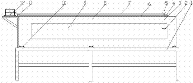
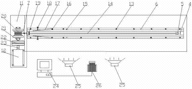
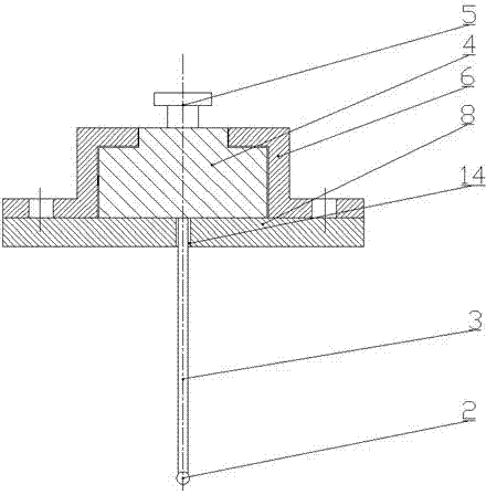
[0018] Such as figure 1 , figure 2 , image 3 As shown, in the present invention, the experimental water tank 8 is horizontally fixed on the experimental support 1 with bolts 10, and the front and back of the experimental water tank 8 are equipped with plexiglass windows 9, and two oppositely arranged "Z"-shaped guide rails 6 are fixed on the experimental water tank with screws 13. 8, along the middle of the length direction, there is a 4mm long through groove 14 on the top of the experimental water tank 8 along the length direction. One end of 3 is connected with the center of bearing slider 4, and the other end of connecting rod 3 passes through the experimental water tank 8 and extends into the experimental water tank 8 through the middle long through groove 14. The other end of connecting rod 3 is equipped with experimental model 2, steel wire One end of 7 is co...


PUM


Abstract

The invention discloses a constraint type experiment supercavity generating device. The front face and the rear face of a water tank are provided with organic glass windows. A through groove is formed in the middle of the upper face of the water tank in the length direction. Two Z-shaped guide rails which are oppositely arranged are installed on the water tank. A sliding pair is formed by a bearing sliding block and the guide rails. One end of a connecting rod is connected with the bearing sliding block and the other end of the connecting rod is provided with an experiment model which extends into the water tank. One end of a steel wire is connected with the bearing sliding block and the other end of the steel wire is connected with a winching wheel in a dragging device. The two guide rails close to one side of the dragging device are respectively provided with a sliding strip. A revolute pair is formed by one end of each sliding strip and one guide rail respectively through a rotary shaft. The side faces of the two guide rails are respectively provided with an adjusting screw. Two pressure sensors are arranged on the guide rails respectively. A high-speed camera and a lighting lamp are arranged in front of one window. The high-speed camera is connected with an industrial control computer. Supercavity generation and development processes around the experiment model are shot through the high-speed camera and accurate and stable experiment speed within a certain range is offered to different models.

Description

technical field [0001] The invention relates to a supercavitation generating device, in particular to a constrained experimental supercavitation generating device. Background technique [0002] When the vehicle moves at a high speed in the fluid, the fluid pressure on the surface of the vehicle will decrease. When the speed of the vehicle increases to a certain critical value, the pressure of the fluid will reach the vaporization pressure, and the fluid will undergo a phase change. The transition from liquid phase to vapor phase is called cavitation. With the continuous increase of the speed of the vehicle, the cavitation phenomenon moves back and expands along the surface of the vehicle, and then develops into supercavitation to form supercavitation. Since the frictional resistance of the vehicle in water is about 850 times that of the air, the application of supercavitation technology can greatly reduce the frictional resistance of the underwater vehicle. [0003] Superc...

Claims


Application Information

Patent Timeline
Patent Type & Authority Patents(China)
IPC IPC(8): G01M10/00
Inventor 陈波彭立兵施红辉黄保乾王昀谢凯
Owner ZHEJIANG SCI-TECH UNIV
Learn More