
Relay control circuit and relay control system

A technology of relay control and relay, which is applied in the direction of program control and electrical program control in sequence/logic controllers, can solve problems such as disordered operation of electronic equipment systems and unreliable disconnection of relay switches, so as to avoid misoperation and ensure normal working effect

Active Publication Date: 2011-03-23
DATONG POWER SUPPLY COMPANY OF STATE GRID SHANXI ELECTRIC POWER
View PDF0 Cites 5 Cited by
  • Summary
  • Abstract
  • Description
  • Claims
  • Application Information

AI Technical Summary

Problems solved by technology

However, according to the principle of electromagnetic induction, the coil will generate a residual induced magnetic field in the opposite direction when the power is cut off, and the residual induced magnetic field will still generate magnetic attraction, causing the switch of the relay to fail to be disconnected reliably, resulting in disordered operation of the electronic equipment system

Method used


Image

  • Relay control circuit and relay control system
  • Relay control circuit and relay control system
  • Relay control circuit and relay control system

Examples


Embodiment Construction

[0011] The present invention will be further described in detail below in conjunction with the accompanying drawings.

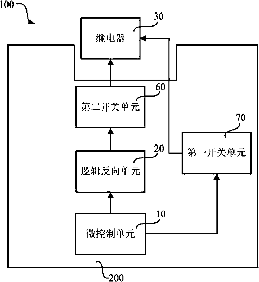
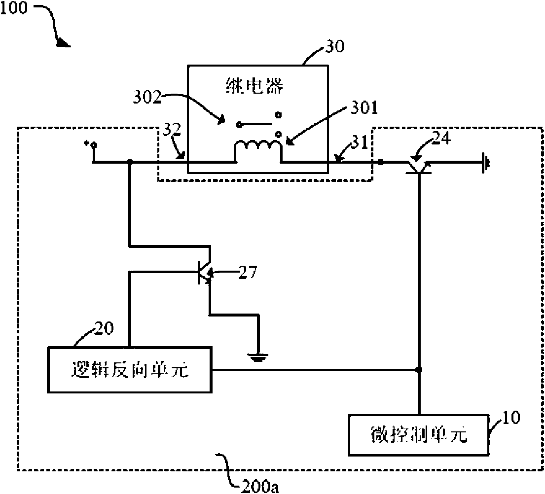
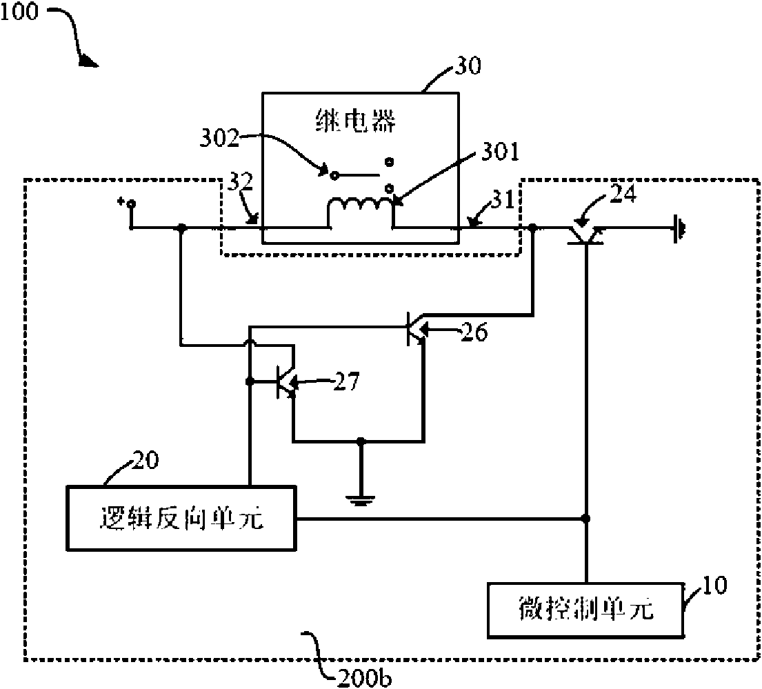
[0012] Please refer to figure 1 , is a block diagram of the relay control system 100 according to the embodiment of the present invention. The relay control system 100 includes a relay control circuit 200 and a relay 30, wherein the relay control circuit 200 includes a micro control unit 10, a logic inversion unit 20, a first switch unit 60 and a second switch unit 70, the following will The application of the relay control system 100 is described in detail.

[0013] The micro control unit 10 outputs the first control signal to the logic inversion unit 20 and the first switch unit 60 . The first switch unit 60 is closed according to the first control signal so that the relay 30 performs an opening action. The logic inversion unit 20 outputs the first logic signal to the second switch unit 70 according to the first control signal. The second switch unit 70...


PUM


Abstract

The invention discloses a relay control circuit. The relay control circuit comprises a micro control unit, a logic reverse unit, a first switch unit and a second switch unit, wherein when the relay control circuit is used for controlling a relay to switch on, the micro control unit is used for controlling the switch-off of the first switch unit so as to allow the relay to switch on, and the micro control unit controls the logic reverse unit to output a first logic signal for controlling the switch-off of the second switch unit so as to allow the relay to switch on; and when the relay control circuit is used for controlling the relay to switch off, the micro control unit is used for controlling the first switch unit to switch on so as to allow the relay to switch off, and the micro control unit controls the logic reverse unit to output a second logic signal for switching on the second switch unit so as to allow the relay to release induced electromotive force produced by a switch-off action through the second switch unit. The switch of the relay is switched off rapidly and correctly and faulty operation is avoided. The invention also provides a relay control system.

Description

technical field [0001] The invention relates to a control circuit, in particular to a relay control circuit and a relay control system using the relay control circuit. Background technique [0002] The popularity of computer technology has significantly increased the demand for relays for microcomputers, and relays with microprocessors will develop rapidly. In the early 1980s, the digital time relays produced in the United States could be controlled by instructions. The combination of relays and microprocessors can form a small and perfect control system. Industrial robots controlled by computers are currently growing at a rate of 3.5% per year. Now, the computer-controlled production system has been able to produce a variety of low-cost relays on a production line, and can automatically complete a variety of operations and testing. [0003] The general relay applies the principle of electromagnetic induction. By energizing the coil to generate magnetic attraction, the togg...

Claims


Application Information

Patent Timeline
Patent Type & Authority Applications(China)
IPC IPC(8): G05B19/04
Inventor 施宗良
Owner DATONG POWER SUPPLY COMPANY OF STATE GRID SHANXI ELECTRIC POWER
Learn More