
Overload limit simulation device

A simulation device and overload technology, which is applied in general control systems, control/regulation systems, instruments, etc., can solve problems such as the inability to truly simulate overload-limited operating states

Active Publication Date: 2015-07-01
STATE GRID CORP OF CHINA +2
View PDF7 Cites 0 Cited by
  • Summary
  • Abstract
  • Description
  • Claims
  • Application Information

AI Technical Summary

Problems solved by technology

However, the simulation model does not involve the simulation of overload limit, and cannot truly simulate the overload limit operating state of the HVDC DC control and protection system

Method used


Image

  • Overload limit simulation device
  • Overload limit simulation device

Examples


Embodiment Construction

[0018] In order to better understand the above-mentioned technical solution of the present invention, a further detailed description will be given below in conjunction with the accompanying drawings and embodiments.

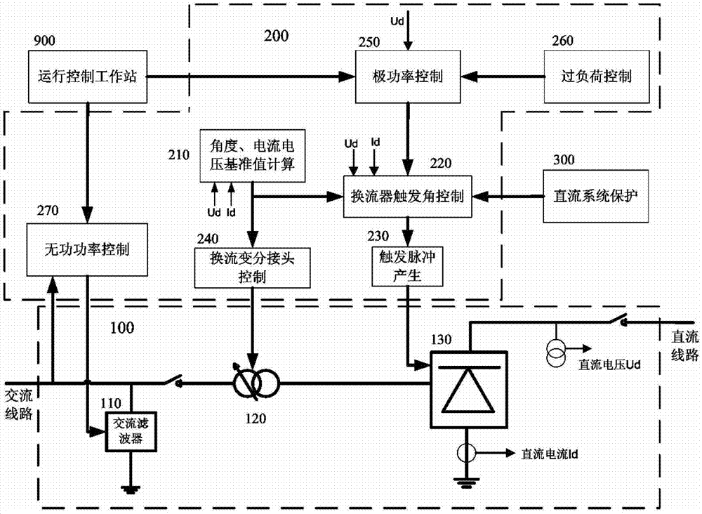
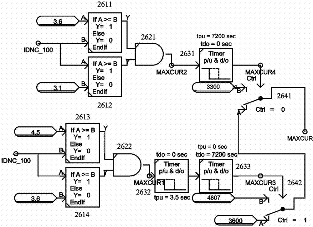
[0019] figure 2 An embodiment of the overload limit simulation device of the present invention is shown, which is used for the simulation of the DC control and protection system of HVDC power transmission equipment. The overload limit simulation device 260 is connected to the input side of the pole power control device 250 of the DC control and protection system . The simulation device of the DC control and protection system of HVDC transmission equipment is as follows: figure 1 shown.

[0020] Such as figure 2 As shown, the overload limit simulation device of the present invention includes first to fourth comparators 2611-2614, a first AND gate 2621, a second AND gate 2622, first to third timers 2631-2632, a first mode selection a switch 2641 and a second ...


PUM


Abstract

The invention provides an overload limit simulation device, belongs to the field of electrical measurement, and particularly relates to an overload limit simulation test device used for high-voltage direct current transmission equipment in direct current control protection system simulation researches. The device comprises a substractor, a first mode selection switch, a speed limiting device, an integrator, a summator, a second mode selection switch and an inertial element. A polar power control device is connected with the substractor and the summator, the substractor is connected with a neutral current signal end of a thyristor current converter, the substractor is connected with the speed limiting device through the first mode selective switch, the speed limiting device is connected with the summator through the integrator, and the output end of the summator serves as the output end of the polar power control device and is connected with a trigger angle control module of the current converter of a direct current control protection system. The device can truly simulate and reflect operation states of a direct current control protection device and provides corresponding simulation results for researches or design of the direct current control protection device.

Description

technical field [0001] The invention belongs to the field of electrical measurement, and in particular relates to an overload limit simulation test device used for simulation research of a DC control and protection system of high-voltage direct current transmission equipment. Background technique [0002] The ever-increasing demand for electricity has led to the development of power transmission systems in the direction of long distance, large capacity and high stability. As the construction projects of UHV AC transmission projects and HVDC transmission projects in various power grid regions continue to increase, the power grids in areas where power consumption is concentrated show obvious characteristics of UHV AC-DC hybrid receiving-end power grids with multi-DC feeds. The power grid structure is tight, and the electrical distance between multiple AC and DC lines is closer. After the UHV and EHV AC systems fail, it is easy to cause multiple DCs including high-voltage DCs t...

Claims


Application Information

Patent Timeline
Patent Type & Authority Patents(China)
IPC IPC(8): G05B17/02
Inventor 崔勇郭强
Owner STATE GRID CORP OF CHINA
Learn More