
Adjusting measurements of the effects of acoustic radiation force for background motion effects

A technology of background movement and measurement results, applied in the field of medical diagnostic ultrasound systems, can solve problems such as large amplitude

Active Publication Date: 2015-07-15
KONINKLIJKE PHILIPS ELECTRONICS NV
View PDF4 Cites 0 Cited by
  • Summary
  • Abstract
  • Description
  • Claims
  • Application Information

AI Technical Summary

Problems solved by technology

However, the magnitude of some of this interference is quite large, and bandpass filtering is not always sufficient to remove adverse effects

Method used


Image

  • Adjusting measurements of the effects of acoustic radiation force for background motion effects
  • Adjusting measurements of the effects of acoustic radiation force for background motion effects
  • Adjusting measurements of the effects of acoustic radiation force for background motion effects

Examples


Embodiment Construction

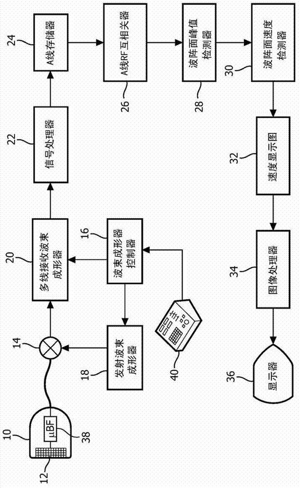
[0016] first reference figure 1 , showing in block diagram form an ultrasonic system for shear wave measurement constructed according to the principles of the present invention. The ultrasound probe 10 has a two-dimensional array 12 of transducer elements for transmitting and receiving ultrasound signals. Two-dimensional array transducers are capable of scanning a two-dimensional (2D) plane by transmitting a beam on a single plane of the body and receiving returned echo signals, and can also be used to pass through different directions in a volumetric (3D) area of ​​the body. and / or emit beams in a plane to scan a volumetric area. The array elements are coupled to a microbeamformer 38 located in the probe, which controls the transmission of the elements and processes echo signals received from groups or subarrays of elements into partially beamformed signals . Through a transmit / receive (T / R) switch 14 , part of the beamformed signal is coupled from the probe to a multi-lin...


PUM


Abstract

An ultrasonic diagnostic imaging system for shear wave measurement transmits push pulses into tissue for the generation of shear waves. Characteristics of the shear waves such as their velocity of passage through the tissue are measured to assess properties such as tissue stiffness. The measurements are compensated for effects of background motion by sampling echo signals from the tissue at different times and comparing the samples to detect the presence of relative motion between the ultrasound probe and the region of interest where shear waves are detected. Sensed background motion is used to adjust measured shear wave characteristics.

Description

technical field [0001] The present invention relates to medical diagnostic ultrasound systems, and in particular to ultrasound systems that use shear waves to perform measurements of tissue stiffness or elasticity. Background technique [0002] A variety of tools have been developed for remotely interrogating the mechanical properties of tissue for diagnostic purposes, using the radiative force of an ultrasound beam to remotely apply force to tissue regions within the patient's body (acoustic radiative force; also known as "push" pulses). Acoustic radiation forces can be applied in such a way that elastic properties can be measured, or locally at the point of deformation by directly tracking the deformation using additional ultrasound imaging, to quasi-statically follow the pattern of deformation and visually identify regions of different stiffness . See, eg, Nightingale, K.R. et al., "On the feasibility of remote palpation using acoustic radiation force", J. Acoust. Soc. A...

Claims


Application Information

Patent Timeline
Patent Type & Authority Patents(China)
IPC IPC(8): A61B8/00G01S7/52
CPCG01S7/52036G01S7/52095A61B8/485A61B8/5276G01S7/5205G01S15/8925A61B8/4488G01S7/52042A61B8/0825
Inventor J·D·弗雷泽H·谢
Owner KONINKLIJKE PHILIPS ELECTRONICS NV
Learn More