Flow pipe for the turbulence generator of the headbox of a fibre web machine and a turbulence generator of the headbox of a fibre web machine

A technology of fiber web machines and turbulence generators, applied in the field of turbulence generators, can solve the problems of large module size, difficulty in changing turbulence generators, flow distribution cannot be changed in small proportions, etc., to achieve the goal of reducing or increasing the number Effect

Inactive Publication Date: 2013-08-21
VALMET TECH OY
View PDF7 Cites 7 Cited by
  • Summary
  • Abstract
  • Description
  • Claims
  • Application Information

AI Technical Summary

Problems solved by technology

Second, turbulence generators assembled by welding are difficult, if not outright impossible, to change once assembled
Third, there is also the challenge of keeping welded turbulence generators clean
The disadvantage of this solution is that the large dimensions of the modules make it impossible, for example, to change the flow distribution on a small scale

Method used


Image

  • Flow pipe for the turbulence generator of the headbox of a fibre web machine and a turbulence generator of the headbox of a fibre web machine
  • Flow pipe for the turbulence generator of the headbox of a fibre web machine and a turbulence generator of the headbox of a fibre web machine
  • Flow pipe for the turbulence generator of the headbox of a fibre web machine and a turbulence generator of the headbox of a fibre web machine

Examples


Embodiment Construction

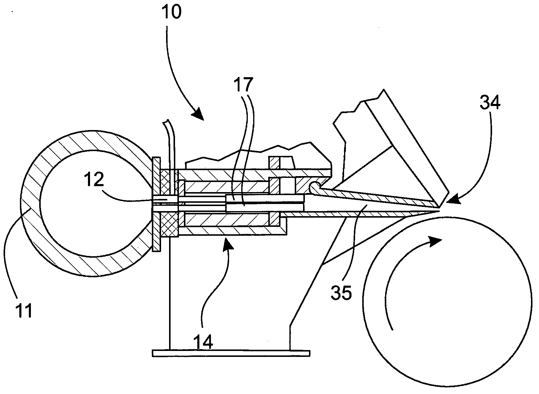
[0021] figure 1 A rough schematic sectional view of an example of a headbox 10 of a fiber web machine is shown viewed from the side. The fiber suspension is led in a manner known per se from the inlet header 11 of the headbox 10 through the manifold grooves 12 to a turbulence generator 14 consisting of several flow tubes 17 arranged in a row and overlapping each other. From the turbulence generator 14 the fiber suspension travels to a slice channel 35 and from there onwards over a schematically shown slice lip 34 to a forming wire (not shown in the figure). In addition, in the discharge opening 35 there may be a plurality of fins (not shown) immediately following the turbulence generator 14 . In the turbulence generator 14, the concentration distribution of the fiber suspension is uniform and any floes that may have formed in the fiber suspension are dispersed. Disperses flocs by creating shear and turbulence in the flow. The turbulence is sufficient to keep the fibers sepa...


PUM


Abstract

The invention relates to a flow pipe for the turbulence generator (14) of the headbox (10) of a fiber web machine, which flow pipe (17, 17') has two ends, an inlet end (13) and an outlet end (15), and between which ends (13, 15) there is a flow channel (16). At least one groove (24) and at least one protrusion (25) is arranged on the external surface (21.1 - 21.4) of the flow pipe (17), in order to attach the flow pipe (17) to adjacent flow pipes (17'). In addition, the invention also relates to a turbulence generator for the headbox of a fiber web machine.

Description

technical field [0001] The invention relates to a flow tube of a turbulence generator of a headbox of a fiber web machine, the flow tube having two ends, an inlet end and an outlet end, with a flow channel between them. The invention also relates to a turbulence generator of a headbox of a fiber web machine. Background technique [0002] Finnish Patent No. 110700 discloses an example of a flow tube, eg a bundle of tubes in a headbox for a fiber web forming machine. A flow tube typically includes two consecutive flow segments of differing surface area sizes so as to form a step. The material of the flow tube is typically eg acid resistant steel from which the desired turbulence generator can be assembled eg by welding. Another option for manufacturing flow tubes is by pressure forming (for example at a pressure of 2000-4000 bar). [0003] However, the manufacture of turbulence generators, eg assembled by welding the flow tubes to each other, involves several drawbacks. Fi...

Claims


Application Information

Patent Timeline
Patent Type & Authority Applications(China)
IPC IPC(8): D21F1/02
CPCD21F1/026
Inventor 萨米·安蒂莱宁扬内·拉皮尤西·瓦萨拉
Owner VALMET TECH OY
Why Eureka
Try Eureka