A Gantry Mobile Machine Tool with Multiple Independent Processing Units

A mobile, machine tool technology, used in metal processing machinery parts, metal processing equipment, manufacturing tools, etc., can solve the problems of no independent full degree of freedom, serious energy consumption, insufficient stiffness, etc., to improve flexibility and processing efficiency. , The effect of ensuring machining accuracy and improving machining rigidity

Inactive Publication Date: 2016-02-10
TSINGHUA UNIV
View PDF5 Cites 0 Cited by
  • Summary
  • Abstract
  • Description
  • Claims
  • Application Information

AI Technical Summary

Problems solved by technology

However, this type of machine tool has the following disadvantages: (1) The X-axis movement of each processing unit is determined by the gantry movement, and the unit itself does not have the independent full degrees of freedom (X, Y, Z, etc.) required for processing, so it is impossible to control the processing unit Independent asynchronous operations (such as hole making and partial milling) are performed on the workpiece area facing, thus seriously affecting the overall processing efficiency of the machine tool
(2) The gantry frame needs to move frequently during the processing of each unit of this type of machine tool, and the frequent start of the heavy gantry frame will have an adverse effect on the machining accuracy and the life of the machine tool, and the energy consumption is serious
(3) The processing unit is usually installed on the outside of the beam or the outside of the column, such as the herringbone frame type gantry machine tool disclosed in the Chinese patent application with the publication number CN202428189U. When the cantilever is too long and the cutting force is large, the rigidity will be insufficient. , causing processing errors

Method used


Image

  • A Gantry Mobile Machine Tool with Multiple Independent Processing Units
  • A Gantry Mobile Machine Tool with Multiple Independent Processing Units
  • A Gantry Mobile Machine Tool with Multiple Independent Processing Units

Examples


Embodiment Construction

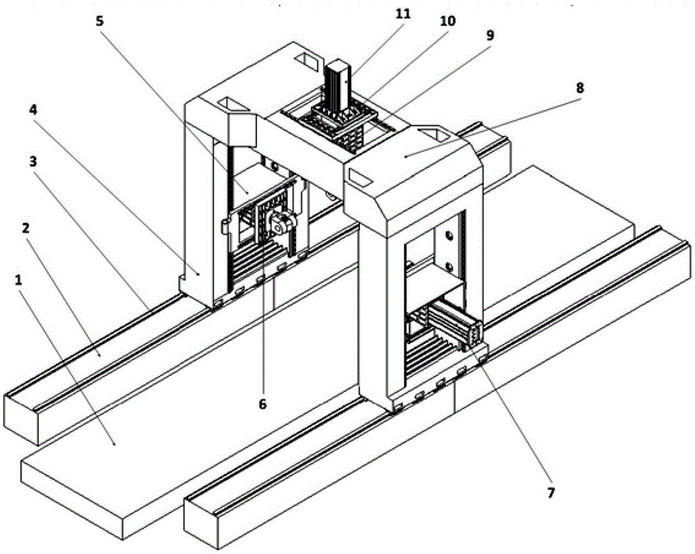
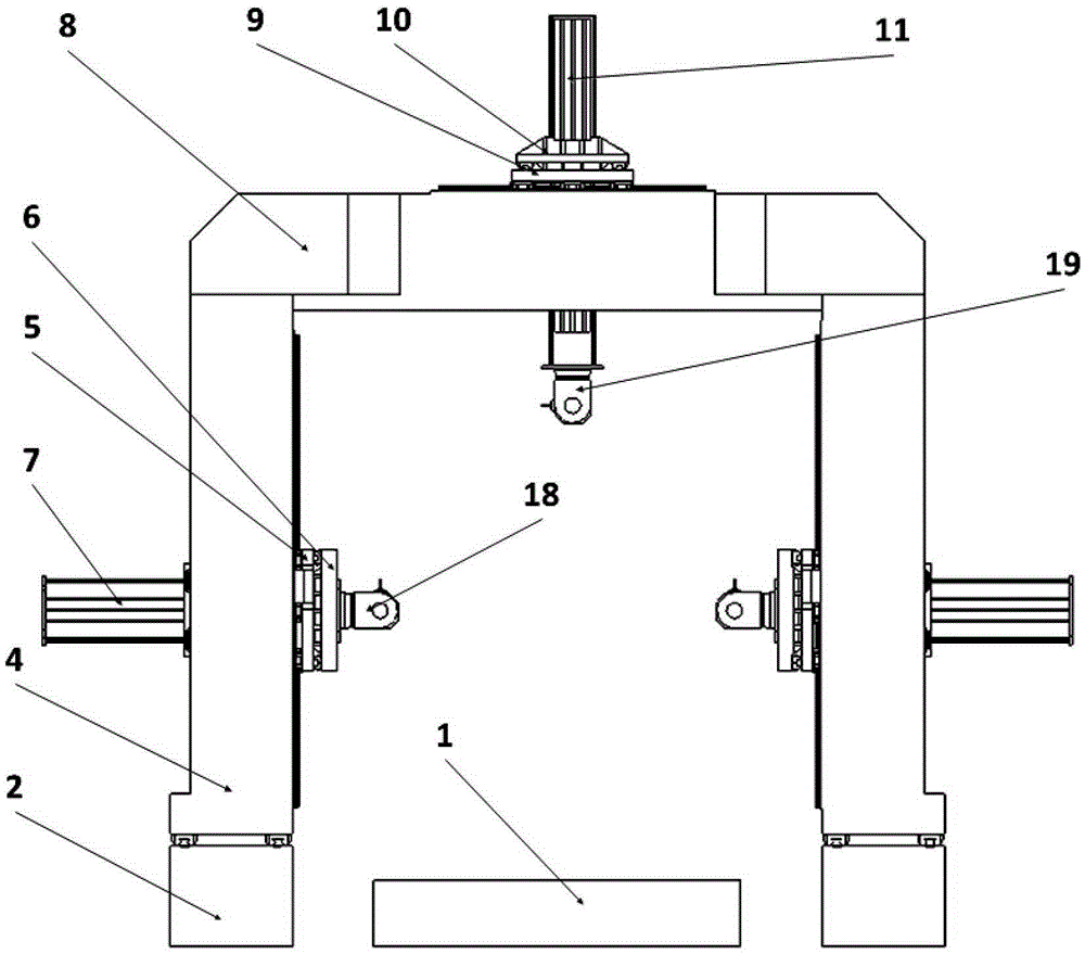
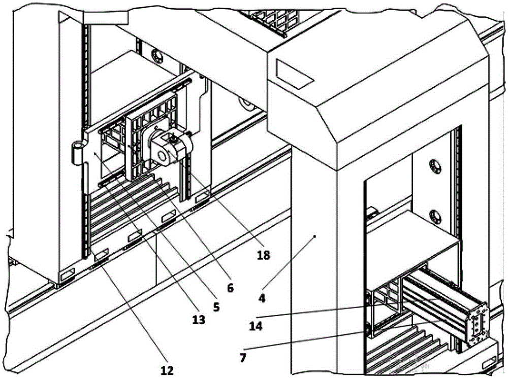
[0011] A kind of gantry mobile machine tool with multiple independent processing units proposed by the present invention, its structure is as follows figure 1 , 2 , 3 and 4, including workbench 1, machine bed 2, column 4, beam 8, column processing head 18 and beam processing head 19. The workbench 1 is placed in the middle of the machine bed 2, the columns 4 are installed on the column guide rails 3 on both sides of the bed, and the beams 8 are installed on the columns 4 on both sides of the machine bed 1. The middle of the column 4 on both sides of the machine tool bed 2 is respectively provided with a through frame. The outer sliding seat 5 of each column is nested in the through frame, the inner sliding seat 6 of each column is nested in the inner cavity of the outer sliding seat 5 of each column, and the column rams 7 on both sides of the machine bed 2 are respectively nested in the column In the inner cavity of the sliding seat 6 , the column processing heads 18 on both...


PUM


Abstract

The invention relates to a gantry moving machine tool with a plurality of independent machining units and belongs to the technical field of machining equipment. The gantry moving machine tool comprises a bench and a body. The body is disposed on two sides of the bench. Columns are mounted on guides mounted on the body. A through frame is formed in the center of each of the left and right columns. A column lower sliding block is nested in each through frame, a column upper sliding block is nested in an inner cavity of each column lower sliding block, a column ram is nested in an inner cavity of each column upper sliding block, and a column machining head is mounted at one end of each column ram. The gantry moving machine tool has the advantages that macroscopic movement can be quickly aligned through a gantry frame; different parts of a workpiece are subjected to asynchronous machining by independent full-DOF (full degrees of freedom) movements of a machining unit and the left and right columns after locking; adverse effect of frequent movement of the gantry frame upon the machine tool is avoided, and machining flexibility and efficiency are improved; and the machining units are in box-in-box structures so that machining rigidity is improved and machining precision is guaranteed.

Description

technical field [0001] The invention relates to a gantry mobile machine tool with multiple independent processing units, belonging to the technical field of mechanical processing equipment. Background technique [0002] In the field of manufacturing, when processing large workpieces, gantry mobile machine tools are usually used for processing. Generally, the processing unit of the gantry mobile machine tool is installed on a fixed beam or a moving beam that can move up and down. In order to improve processing flexibility and processing efficiency, processing units can be installed on the columns on both sides, such as the compound gantry machine tool disclosed in the Chinese patent application with publication number CN202240461U. However, this type of machine tool has the following disadvantages: (1) The X-axis movement of each processing unit is determined by the gantry movement, and the unit itself does not have the independent full degrees of freedom (X, Y, Z, etc.) req...

Claims


Application Information

Patent Timeline
Patent Type & Authority Patents(China)
IPC IPC(8): B23Q1/01B23Q1/25B23Q1/44
Inventor 周凯钱琪吕江伟
Owner TSINGHUA UNIV
Why Eureka
Try Eureka